


Tomatobro
-
Posts
1,251 -
Joined
-
Last visited
Content Type
Profiles
Forums
Gallery
Events
Blogs
Posts posted by Tomatobro
-
-
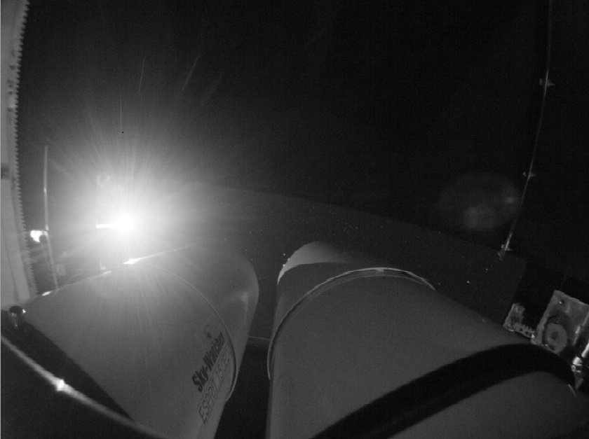
I had my EQ8-r delivered in October 2021. It replaced my EQ6 pro. Machining the adapter for the mount required me to lift the EQ8 on and off the pier about 8 times which put my back out for about 10 days or so.
After about 50 hours of use I adjusted the RA backlash which was straight forward. There is a tiny bit in the DEC but the polar alignment is so good I have not done anything with it.
My main concern was what would the build quality be like as it was the first batch out of the pandemic but I could not fault it.
-
 1
1
-
-
As per Malc's suggestion you might find TeraTerm (its free to use) for the comms check easier to use. In settings select the com port number shown in Device manager (should default to the correct settings) and in terminal set to local echo.
The led is being powered by the usb port supply to the serial chip in the cable.
-
Should be possible to set up and test in daylight
"look Igor it moved"🤖
-
1
-
-
10 hours ago, Anthonyexmouth said:
voltage fine, and all appears ok in device manager.
OK, having made a note of the Com port number that appears when the cable is connected in Device manager) then connect it to the mount, open EQMOD on the laptop and see if the comport number (the baud rate and config also) in the EQMOD matches. If not then put the correct number (s) in the box and see if it connects to the mount.
If still unresponsive (even if it connects) then a repair of the board is most likely
You may well be right regarding the red led. On my EQ6 with power applied and the serial cable connected with the power switch off the LED is off
-
The steps I would go through are these.
Use a multimeter and check at the power cable tip that you have at least 12 volts
I think you are using a FTDI serial cable. Power up the laptop and with the cable disconnected at the mount end plug it into a usb port. Do you hear the Ping note from the laptop?
Now (with the cable still connected just toi the laptop go into Device manager list the com ports. Make a note of what is connected, then pull out the cable. The device manager com port list should reset and one of the com ports will be missing. Check your list of what was present before and plug in again the cable. Does the com port reappear?
Report back what you see
-
On 20/07/2022 at 19:33, Anthonyexmouth said:
When you remote in, do you have your chosen apps start on boot or do you manually start them?
After remote desktop connects I start each APP from scratch.
-
1
-
-
I also clicked on the "notify me when available" but with demand outstripping supply I guess it did not meet the "when available" criteria.
-
 1
1
-
-
When I set up my latest NUC mini pc from what I can recall the plate solving data files can be copied but all the rest were downloads and fresh installs.
NINA and PHD requires a configuration set and a calibration. Sharpcap will need its license file copying across.
At least you will start with all the latest upgrades👍
-
Sounds like you have the same issue that I had. As I moved towards a fully automatic system (using an EQ8-r) I found that over a long session the camera would disconnect and would not recover. To fix I installed a Startools 4 port 3.0 unit ( industrial grade powered )and connected the camera to that. that gave me (from the USB 3.0ss port on the computer) a connection to the Startools unit and then port one direct to the camera. The camera has not disconnected once with this setup.
-
My understanding of the EQ8 usb hub is that it has to be powered by 12 volts so do you have 12 volts plugged in at the input side?
-
58 minutes ago, tomato said:
I now know just how hard it is to get a result
We both have observatories so are a bit rusty in setting up from scratch an EQ6-r and Altair 4 inch. Together with laptop software issues it was a bit of a challenge. We allowed two hours before the first ISS pass to get organised and we missed it by a few minutes. We practised on other satellite passes before the next ISS pass. I have not seen the results yet but we have some images with a bit of luck
-
1
-
-
A wire (usually the centre one) has broken free and shorted to the negative. Take a Stanley knife and split the moulding to reveal the connections and you will see what I mean. I have seen this kind of failure before.
If the connections are ok then its whatever it was connected to is the problem.
-
Watched a very large prom (arrowed). Part of the prom became detached as per lower sketch

-
11
-
 1
1
-
-
Either of those two piers will work just fine. I have been involved in the construction of two observatories, the first using a Pulsar pier and the second a DIY pier. The Pulsar pier supports a Mesu 200 mount and two SW esprit 150 refractors with all the accessories (about 70kg).
Savings can be made by going down the DIY route but it depends on what you are willing to tackle.
You may also need an adapter for the pier top to take the mount.
-
Secondary support arms?
-
The dual rig is operated remotely and has two small stepper motors one each for the Samyang lens. I only had one black version Hitec stepper motor controller available so there is a comm port switched relay bank to switch the Hitec focuser output from one stepper motor to the other.
With the comm port switched one way the ZWO can be focused and then switching the comm port the other way the Atik can be focused.
The rubber focus grip ring on the lens has a 2mm pitch which looks as if the lens designers had in mind a toothed belt driven focuser.⭐
-
1 hour ago, Gonzo said:
That's a cool setup there you got.
Thanks. Although I allowed for the rotation of each camera/lens for image alignment what surprised me was (despite my careful engineering) just how much left/right and up/down movement was required to get the star fields to align so keep this in mind when putting the rig together. At least once its done its done so its not a maintenance issue.
-
This Dual setup has an ATIK Horizon 2 with an IDAS NBZ filter on one side and a ZWO ASI1600 mono with filters on the other. Lenses are Samyang 135mm F2
It works reasonably well but given the budget I would change the cameras for Rising Cam OSC both with the IDAS NBZ filters
The ATIK and ZWO cameras have the same sensor but for the OSC version in the Atik
-
2
-
-
On a Pulsar dome controller operated by N.I.N.A software there is a whole host of measurements that have to be programmed in in order for the controlling software to position the dome to match the scope position. Steve Richards did a write up and spread sheet to help with the measurements.
I built a controller for a early Pulsar dome which used two lasers mounted either side of the dome aperture which sensed when the scope broke the laser beam and nudged the dome round to re-establish the laser light.
Its also possible to wind a coil round the end of the scope and use a switching circuit to create a alternating magnetic field which can induce a current in a coil of wire looped round the shutter aperture. Electronics sense the rising current as the scope approaches the edge of the aperture and nudges the dome round to null the current.
I built a mock up of this method but settled on the lasers illuminating light dependant resistors as a reliable method. I did have to write a routine that allowed for moths flying through the laser beam in that the beam had to be broken for a number of seconds before the dome got nudged.
-
1
-
-
Tomato posted this picture which should give you some comfort

-
When I had a bad back I stopped using my EQ6-r for a while and got a star adventurer. Its a cracking mount and I used it with a variety of cameras (DSLR and others) and scopes including the Samyang 135.
The problem you will have is finding the object to photograph. A laptop with plate solving software sorts this problem out but its best with a dedicated astro camera as this will have the sensitivity and high speed that will make it a pleasure to use.
With the camera and lens pointing to roughly the correct bit of sky, expose and plate solve, make a note of the declination number and adjust the declination axis till the numbers match with the object of interest. Keep going through this loop but don't be tempted to alter the right ascension till the DEC is correct.
Then its a matter of adjusting the RA till the object appears on the laptop screen.
I resisted using plate solving software for ages but would not be without it now as it saves a great deal of time.
-
1
-
-
My remote (well at the bottom of the garden) observatory runs two Intel NUCs and up until the last couple of months the Remote desktop connections have been super reliable but recently the latency and dropouts have become a real pain. Thinking that it might be a frequency drift issue due to the high temperatures I tried many things to see if I could improve the situation.
With everybody out the house I removed the NUCs into the office right next to the router and did some load testing by running all the software and watching YouTube videos. It all seemed to be ok but I noticed that sometimes when I connected NINA or Sharpcap I could hear a voice message from the smart speaker in the kitchen.
To cut a long story short the cause of the latency and dropouts is down to the smart speaker. Disconnecting it and reinstalling the NUCs back in the observatory the remote desktop connection is once again reliable as an anvil. Seems like the smart speaker takes up quite a bit of WiFi bandwidth.
-
1
-
-
I had a go at improving the "look" of the sketch. I used 3D paint to create a colour disc with the light direction tool to create a PST style image.
I tried using different colors and inverting to get it right but the original looked the best with red, yellow and brown pencils.
Anyway here is the end result
-
8
-
1
-
-
two large filaments seen today
-
3
-


Eq8 mount
in Discussions - Mounts
Posted
The question is a bit unfair on the EQ6 as it was already a bit overloaded hence the move to the EQ8.
With the 10 inch tube RC, Altair 60mm guide scope, remote focuser, 7 position filter wheel and cameras last night PHD reported
RA 0.12 (0.39")
Dec 0.06 (0.19")
Total (0.43")
RA osc 0.20
From memory on the overloaded EQ6 the RA would be around 0.85, and the DEC about 0.65 on a good night.
Hope this helps