


Ant
-
Posts
28,005 -
Joined
-
Last visited
-
Days Won
5
Content Type
Profiles
Forums
Gallery
Events
Blogs
Posts posted by Ant
-
-
Ordered a new OTA and some tube rings (one Steve stocked and the other he didn't) on Monday.
Both arrived on Tuesday

Ant
-
I ordered an Ambubble from FLO, at around lunch time on thursday.
By Friday at about 9:30am it arrived on my desk at work.
Fantastic service.
The only snag is that it's a birthday present and I'm not allowed it yet.
But it looks damn good in the plastic bag

Ant
-
I recently upgraded my scope with the Syncan upgrade. Purchased from the nice man at FLO
The following is a step by step run though of the installation.
Hopefully someone will find this usefull.
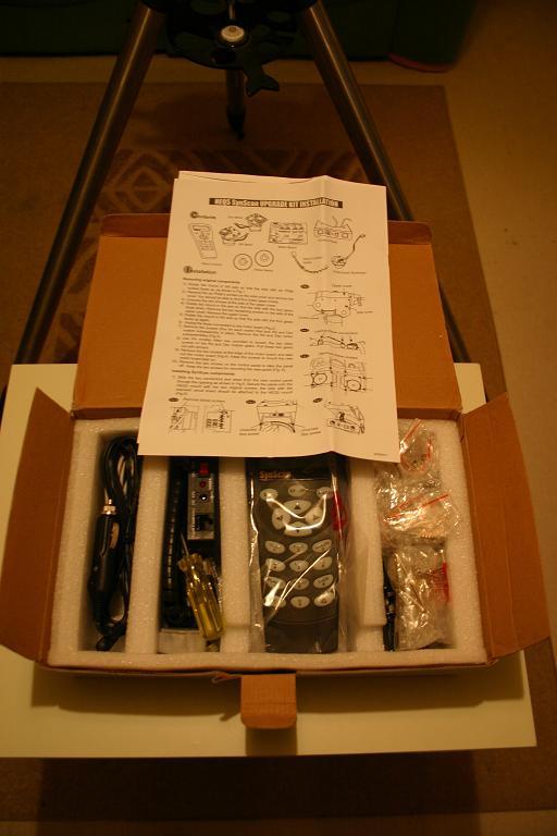
A box arrives

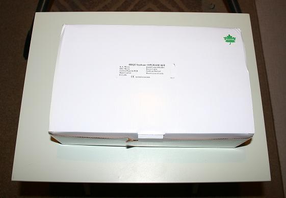
(click to enlarge)
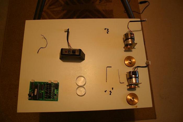
Step 1
I suggest laying everything out neatly - the only thing that I needed in addition to the tools supplied was a pair of long nose plyers. The plyers helped in in removing the brass wheel from the RA and DECaxis. Having long nose plyers helped in retreiving the little screws that hold in the motors - they are a little buggers when they slip out of your fingers. Also remember that some of the things that you screw in are delicate (PCB and covers) and do not need to be as tight as you can make them, just tight will do
. Here is the box contents

(click to enlarge)
all laid out
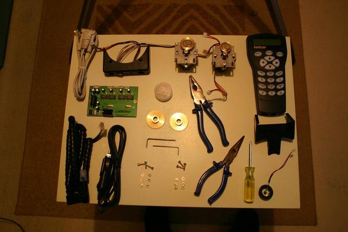
(click to enlarge)
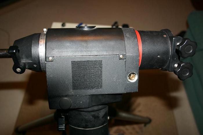
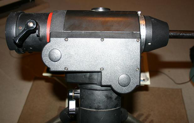
Step 2
Undo the 6 screws that hold on side panel as shown in this image.

(click to enlarge)
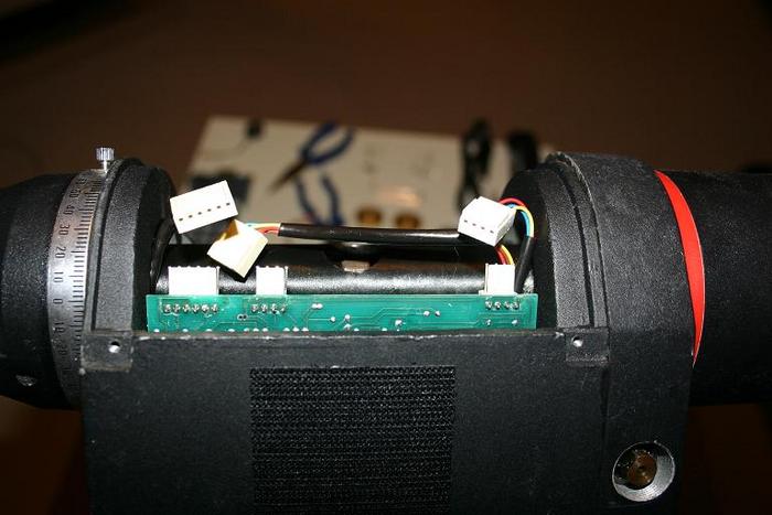
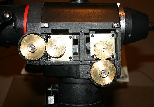
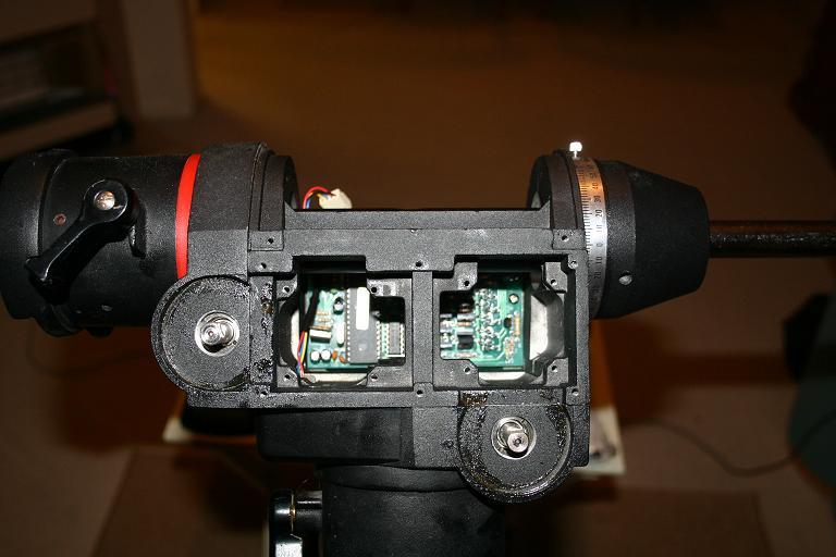
This shows the motors

(click to enlarge)
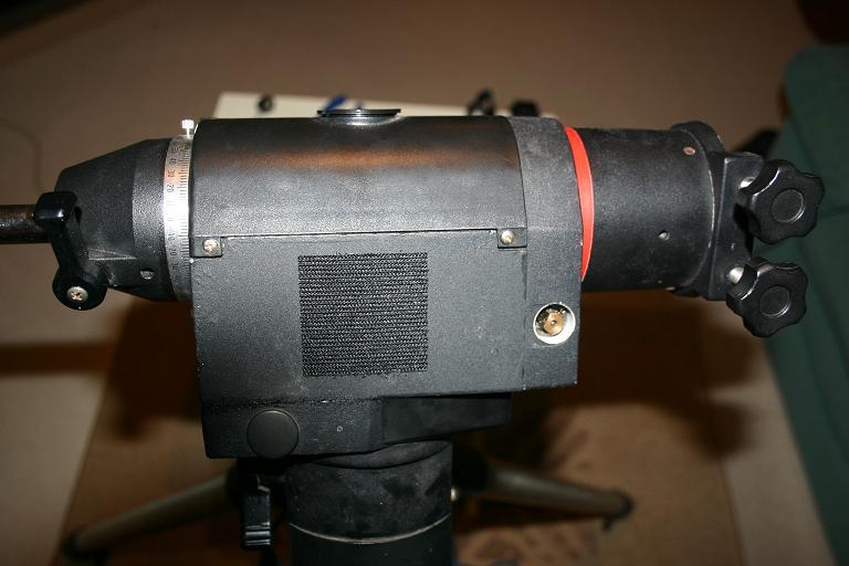
undo the two screws holding the top (curved) cover on. Then spin the mount round 180 degrees and undo the screws shown in this image.
(click to enlarge)
Step 3
Shown in this image are the items that you have removed laid out nicely - you are going to need these later.
Step 4
(click to enlarge)
You need to remove the motors, First you need to loosen the screws that hold the motors in place - just a little. Then you need to use the allen key to loosen tiny little bolts that hold the brass wheels in place. Once loose you can pull the brass wheels off I had a little trouble with one and had to use the plyers - remember that there are two little bolts per brass wheel and they both need to be loosened.
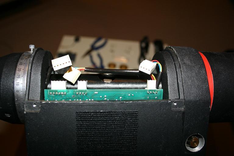
Once the brass wheels are removed you can then spin the mount over to remove the connectors from the PCB
(click to enlarge)
Finally undo the screws completely that hold the motors in place, gently pull the motors out - remembering that the wires have connectors on the end and pulling hard could damage either the wires or the internal connection.

(click to enlarge)
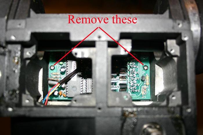
Step 5
Now you have to remove the PCB. There are two little screws that hold the PCB in place, as shown below.
These screws are needed for the new PCB, do not lose them.
(click to enlarge)
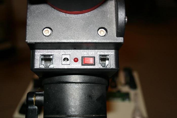
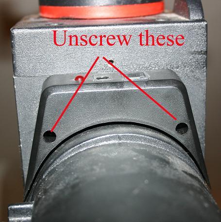
Step 6
Now you need to remove the control panel. There are two little screws underneath. These screws are also required for the new control panel.

(click to enlarge)
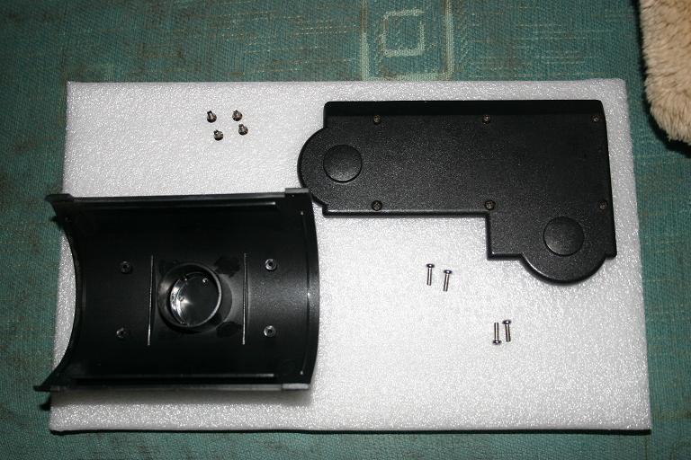
You are now at the half way point.
Here is a picture of the bits you have removed that you are going to need again. You'll notice the screws for the first panel you removed are still in the holes on the panel itself. So you have the Curved top panel with screws, L shaped panel with screws, two little bolts from the PCB and two little bolts from the control panel.

(click to enlarge)
Also you should have left over the following peices...
(click to enlarge)
Step 7 add the control panel, poke the wires through the hole and ensure that they come out on the opposite side to where the motors go. Use the two screws that you saved earlier.
(click to enlarge)
Step 8
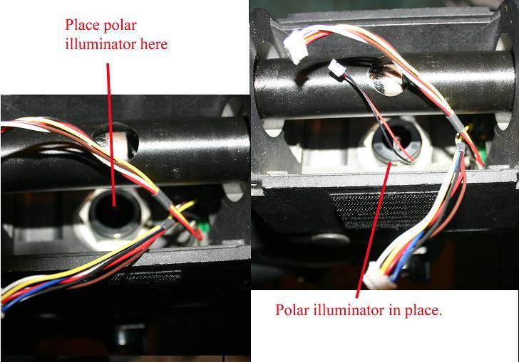
Add the polar scope, this just pushes in place . You can see the wires from the motors in the correct position.

(click to enlarge)
Step 9
Now add the PCB back in place, using the two screws saved from earlier.
Step 10 add the new brass wheels - they are both the same. Do not tighten them to start with as they need to be adjusted to match the motors later.
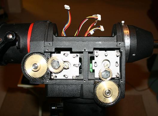
Step 11 now install the motors - they will only fit one way. The motors have two differnt size brass wheels, so you cannot get them the wrong way round. But as you look at the picture below the DEC motor has the larger wheel and goes on the left. The RA motor the smaller wheel and goes on the right.
As you offer up the motor to it's new home you need to feed the wire through so that you can get to it from the other side, it's a little fiddly but not hard, this needs to be done for both motors. Once the wires are poking out the other sixe, you can start "screwing" in the allen key bolts. Remember to get all the bolts started before tightening the first. Make sure that the wheels are fully engaged without being over tight.

(click to enlarge)
Step 12 attach all the connectors to the PCB, all the connectors are different sizes except two and therefore will only fit in one position, the PCB is marked for the other two.
Step 13
Add the grease on the gears, spin them round by hand to ensure that they are greased all the way around.
Step 14
Add the curved top cover back in place.

(click to enlarge)
Step 14
Add L shaped panel back on.
Step 15
Attach the handset holder to the accessory tray.
Step 16
Plug in the handset.
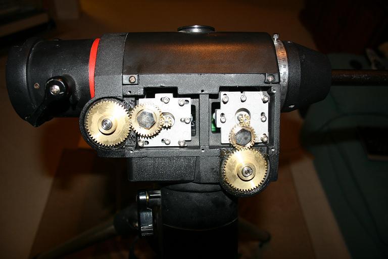
Finished
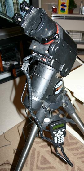
(click to enlarge)
-
 6
6
-
-
This was taken with a SC1 modified webcam with a 6" F5 OO Europa. On a HEQ5 mount.
Have no idea of exposures or processing...
I don't think this is the absolute first, but would have been within a week or two of starting and this is the first object ever imaged.
I can remember the feeling as the first frame appeared on the screen - I was like a dog with two tails...

Ant
-
Thanks for this Matt. This is now a sticky and all comments (except mine) will be in a defferent thread - so this thread stays nice and tidy!!!
Amt
-
1
-
-
Hi Captain Vallo,
For the events side of things try the following
http://ukastronomers.com/#browse/events/ajax/true
We are trying to make this as up to date as possible.
For the others, it takes time to write the primers, but rest assured that they are being added to all the time.
Ant
-
1
-
-
Thanks for the reminder.
I must re-install the SETI software. Might do that tonight!
Ant
-
I have to agree that it is the way in which companies deal with problems that show if they are good or bad.
Any old idiot can take your money - thats the easy part... It's getting the communication, delivery and after sales service right that's that hard part.
If something goes wrong - it's how you deal with the problem that counts.
Nowadays we live in a commodity world - most of the stuff available from one company is available from others - what makes a company stand out? After sales service. This can range from letting people know when things are going to be late to dealing with faulty or missing items.
I bought something from Steve back in June. I received an email telling me it was going to be late (not a problem, providing I know).
When the delivery arrives one of the two items are missing. I called steve and asked when I was going to get it and he said that he had already posted it (a month earlier). He said that he would post another one out the following day. He did and it arrived 36 hours later!
For after sales service, you cannot get better than that!
Ant
-
1
-
-
My PC is connected 24/7 - only restart it when it starts to play up!
I have around 20 or 30 failure mesages in the log.
Guess I need to just be patient.
Cheers
Ant
-
Cheers Mark,
At least I know that it's a problem at my end now and not there's...
I'll have a little investigate.
Ant
-
I've managed to download a lot of units. The PC has completed about 10 now abut none of them will upload!
Anyone else have this problem?
Ant
-
Looks like the end of the problems is in sight!
I can't double check to see when the last time I received work from SETI! I'm sure that it was OK on the 4rd - but that would seem impossible - maybe I was fibbing!

Ant
-
It's all working for me.
The website is up and running, just check our team stats...
Also my other PC collected some new work this morning.
Ant
-
Mind? Not at all mate. Everyone welcome.
Cheers
Ant
-
mine's working fine WH.
Just recently installed the software again and been working fine ever since.
Ant
-
It's strange that some people have issues with it while others don't.
I've always had Seti set to run all the time. Never had any problems - strange...
Hope that you manage to get it sorted WH - this does remind to reinstall the software after the OS re-install.
Ant
-
If you just sit and watch task manager then it will take 99% of your processor. But get something else running in the background - or even just wiggle the mouse around on the screen and you'll see the percentage drop.
BOINC is a very low priority program and as such will only use whats left of the processing power, you could set it to only run when the screen saver kicks in - then you know that it won't be running while you're using the PC>
Ant
-
Welcome to a new section of SGL.
The whole point of this section is for members to post images, and receive comments on why it went wrong.
DO NOT get upset if someone criticises your image / equipment / technique - thats the point.
We also want constructive criticism only. You will continue to receive comments and advice elsewhere within SGL but in here it will be assumed that you are not happy with your image and actually want advice on what might have gone wrong.
Enjoy.
Admin
-
I'm running it on a Dell PIII 800 - not a quick machine by todays standards and I have no problems at all.
Strange...
Cheers for trying guys...
Ant
-
We have loads of new members since this thread was last updated.
Do any of you guys / girls fancy joining our team and searching for ET signals?
It's free, just download a little software and your away!
Ant
-
As you can see from my Avatar I thought it was funny!!!
Cheers Daz - I mean Gaz - [removed word] got it right the first time
Ant
-
I've had a hard day - lost my job yesterday
Here's the link to our team, just little old me in it at the moment.
http://setiathome.berkeley.edu/create_account_form.php?teamid=117875
Sorry Gaz,
Ant
-
1
-
-
We've already set up a team Daz, I'll dig out the link.
Ant
-
1
-


Focal reducer on newtonian
in Discussions - Cameras
Posted
It works exactly the same for Barlow.
I have a 2" 2x barlow. But the lens part unscrews and I can screw it into the 2" adapter on the Canon. This changes it to about a 1.4x barlow (that figure is an educated guess).
The closer to the chip / film / EP the less of an effect.
Ant