-
Posts
4,141 -
Joined
-
Last visited
-
Days Won
3
Content Type
Profiles
Forums
Gallery
Events
Blogs
Posts posted by fwm891
-
-
Nice one Adam
👍
-
 1
1
-
-
-
I'm having a one person debate at the mo and can't seem to come to any reason for / against in either direction.
I'm currently building a 16inch f5 dob and wondering whether I need a finder scope. I will have a x1 rdf and my though is/has/was to use a 40mm eyepiece as a 'finder' before switching to a higher mag. I've been trying most eyepiece makes/varieties in simulations to get a 'feel' for what fov such an eyepiece would yeald. A lot comes down to eyepiece design really wide fields come at a huge price and are not being considered. I like the ES 68° 40mm apart from it's weight, the pentax XW 40mm also seems a good option...
But would a finder scope be a better option especially for hopping to targets...
Any thoughts please especially from the larger scope brigade out there - what is/was your solution to getting to your chosen target.
Cheers
-
Started making up the secondary mirror tilt/collimation assembly. The lower plate in the photos (with the 4 cap head screws) is fixed the upper plate is allowed to tilt/tip it's movement resisted by 3 compression springs and activated via 3 screws. The actual adjustment screws will be 'tool free' the cap heads shown are temporary to let me check the movement. As a guestimate at the moment there appears to be circa ± 7-8 degrees of tip/tilt movement, more than enough to collimate the secondary.
The angled plate still needs some shaping and a few holes drilled/taped to take the secondary elliptical back plate.
Any resemblance to a cuttle fish is purely by chance....
-
Started out last night doing a guiding assist check in PHD2 before trying a few subs on M27. I captured in SGP and decided to set my usual cooling on an ASi533 OSC at -12° C and just start exposing while the sensor cooled. I noticed that some of the pixels were bordered by a black ring - very worried at tis point as I'd not seen anything like this before. Decided to let the captures continue and noticed that the rings faded. They didn't completely disappear until well after the sensor was showing it was at -12° C.
First 3 frames are sequential final frames some 10 mins after the others. All subs are 5 mins.
Anyone seen this effect before.
-
3 hours ago, Horwig said:
Really nice looking project, and nice looking drawings as well, what software do you use for the drawings?
Huw
Thanks Huw. I use Photoshop. I draw everything full scale but drop the resolution down to 100 dpi to keep file sizes manageable. I use multiple layers to build up individual parts or bring parts togtehr to form a complete instrument. It has a feature to auto align layers to vertical/horizontal centres or top/bottom, left/right edges then link or merge them together. The version I have is old now CS3 but for this type of project it's ideal.
-
 1
1
-
-
I'm primarily an imager but once everything is running I like to sit back with a pair of bins and just look up...
Making myself a dob at the moment to get more detail from areas found in the bins.
-
 2
2
-
-
Made a start on some of the woodwork for te mirror box. Back and sides are from 18mm birch plyoood, front baffle is 12mm birch plywood. There are 3 recesses cut for fans and other apertures acting as vents to allow general air movement and as exhausts when the fans are running. Corners have been dovetailed. At present everything is 'dry' fitted to allow easier access/assembly/disassembly.
Through holes have been cut for the brass collimation nuts, small recesses (3) near each collimation nut will locate compression springs. The compression springs should provide enough push to avoid needing locking screws.
More to follow...
-
 3
3
-
-
1 hour ago, Laurin Dave said:
Lovely images, particularly like the Trifid.. which must be very low
Dave
@Laurin DaveThanks Dave - Yes very low and just a gap between trees which is why it was shot over a number of nights. M16 and 17 are higher and miss the worst of the trees so I've been able to get thhose captures in a single session.
Thanks to Tooth_Dr too, @tooth_dr.
-
 2
2
-
-
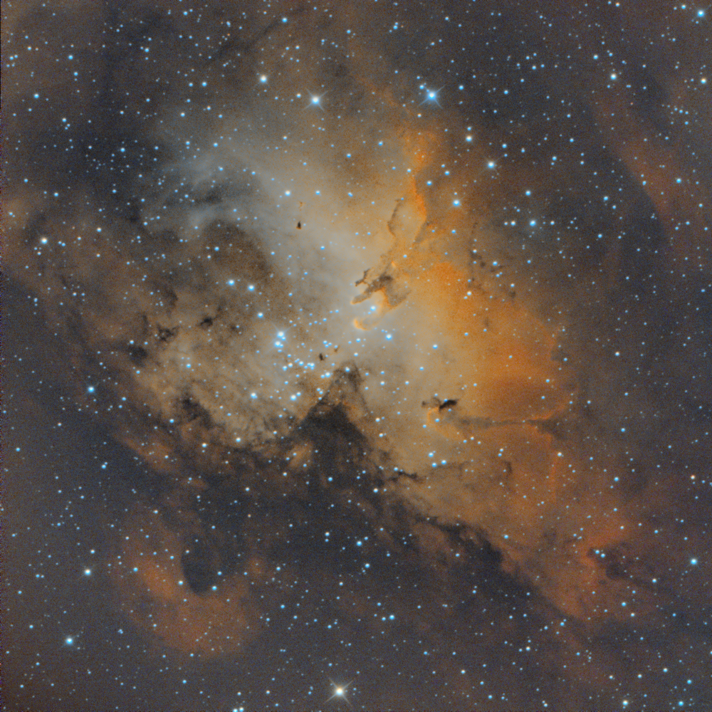
These images were captured this week, others still to process but I have to say I can't remember the last time I've had 4 nights in a row - magic.
Subs were all 300s in length for M16, 17 and ngc6888 (numbers in the file names) M20 was shot over 3 nights, mainly using 300s but there were a few at 120s and 2 at 600s in the mix. M20 was shot using a Baader UV/IR cut filter initially then I switched to an IDAS NBZ on the third night (last night).
TS/GSO 8 inch RC with 0.67x reducer. ASi533 MC Pro OSC camera @ -12 C
Processed in PI.
Hope you like.
-
 15
15
-
-
18 minutes ago, Robert72 said:
Hello, nice project. I was wondering what you were using for your layout drawings? I am also using the Baader Steeltrak in my project, and could do with that dwg for my layout.
Hi Robert72, I've used Photoshop for all the drawings. I set scaling/resolution at 100 dpi which keeps the file sizes down. I tend to use layers a lot with these drawings and build things up by creating smaller drawings at the same resolution and transferring them to build up a full sized scope image. That way your working with smaller files making life easier all round. You can probably do the same with Gimp2 but I don't have any working knowledge of Gimp.
I hope that helps
-
 1
1
-
-
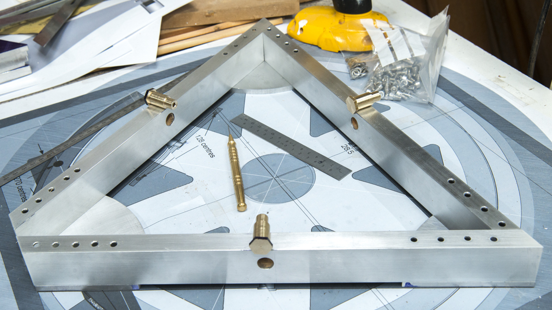
Managed a bit more metalwork today. I've made the pivot shafts with a modification. I've made the pivot end of the shaft 10mm rather than the 8mm originally planned. Also given some of the ali parts a light clean-up with #320 W&D paper (dry).
The holes in the top of the box sections are for Allen key access.
Other mod: I've inserted a snug fitting piece of timber inside each of the aluminium Box sections: a) provide extra support where the pivot shaft goes through the ali box section b) help to deaden any vibration within the framework.
-
 2
2
-
-
Short answer No. The M42 thread (T thread) is used to attach the camera to a lens/telescope. You will need an adapter of some sort to take a 1.25" filter. I used an old cheap 1¼" barlow with the lens removed to do that. They have a M42 T thread at one end and a 1¼" filter thread at the other...
-
Great build - Mine is similar for a 10" dob. To be upgraded for a 16" build currently under way.
-
 1
1
-
-
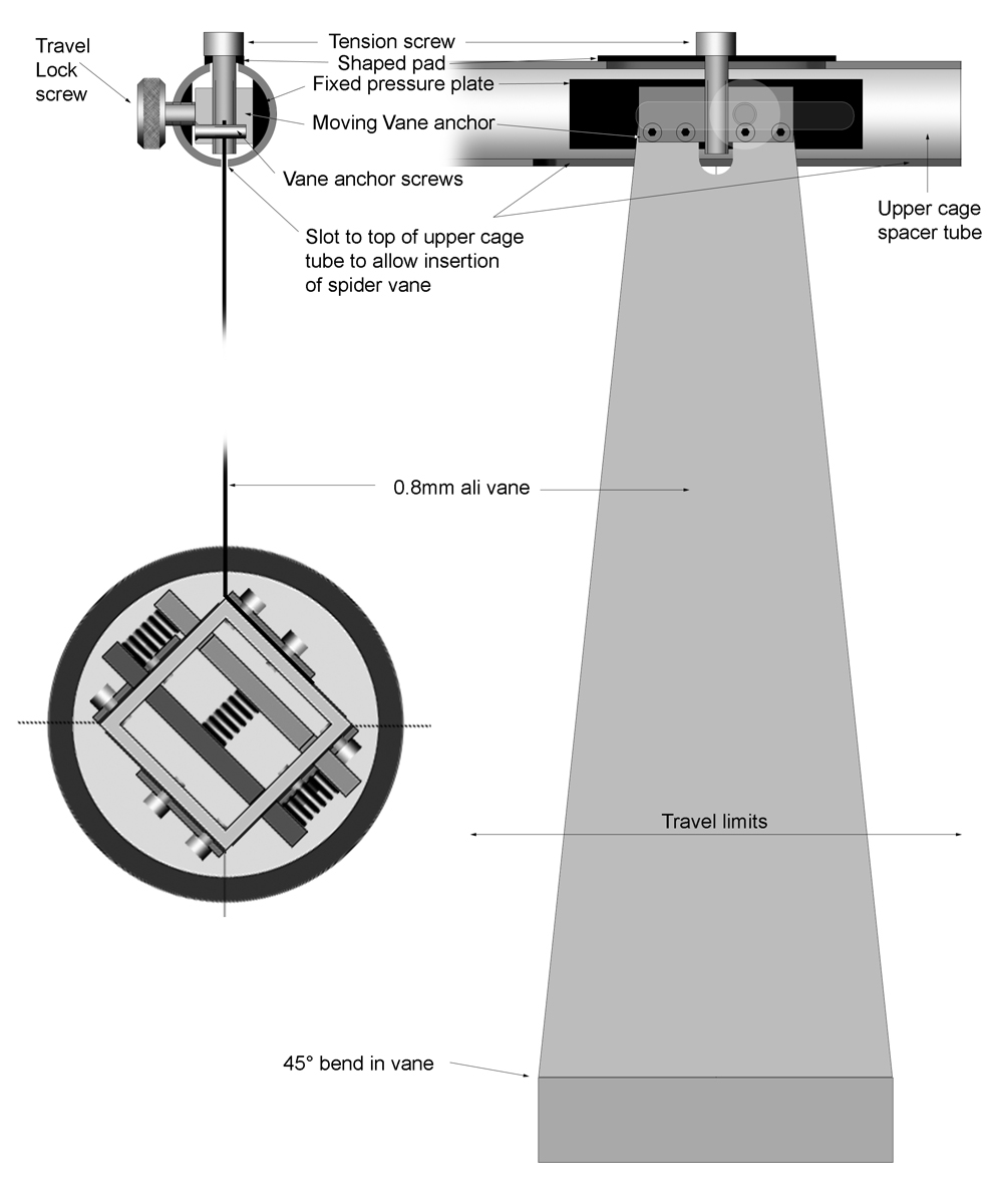
My initial thoughts on the axial adjustment of the spider to position the secondary under the focuser.
The drawings are not engineering style nore are they photos so some might find them confusing but they work for me.
The top left shows the end view into one of the 4 upper cage spacer tubes. The black fixed pressure plate is bonded to the inside of the tube (probably epoxy but may suppliment with m/c screws). The vane itself is held in the moving Vane anchor block with 4 m/c screws, there is a tension adjustment screw which passes vertically through the Vane anchor block to apply tension and radial positioning of the assembly.
The travel locking screw passes through a shaped 'nut', tightening the travel lock applies pressure via the screw to the Vane block and outwards against the tube wall. This will allow circa ±20mm to the whole assembly inside the upper cage.
Lower left is an end view of the secondary adjustment assembly giving tip/tilt adjustments via compression springs for collimation.
View on the right is my attempt to show the same from a different angle. The pale slot outline against the fixed pressure plate is the slot the Travel lock moves in.
TBC...
-
 1
1
-
-
A RASA8 has a back focus of 25mm when measured from the M42 adapter or 28.7mm if measured from the reference surface (i.e. M42 adapter removed).
You should download the 'White Paper' from the Celestron web site, it gives all the specs and drawings for the RASA scopes.
-
Next job on the list:
The pivot bar, pivot shaft and triangles.
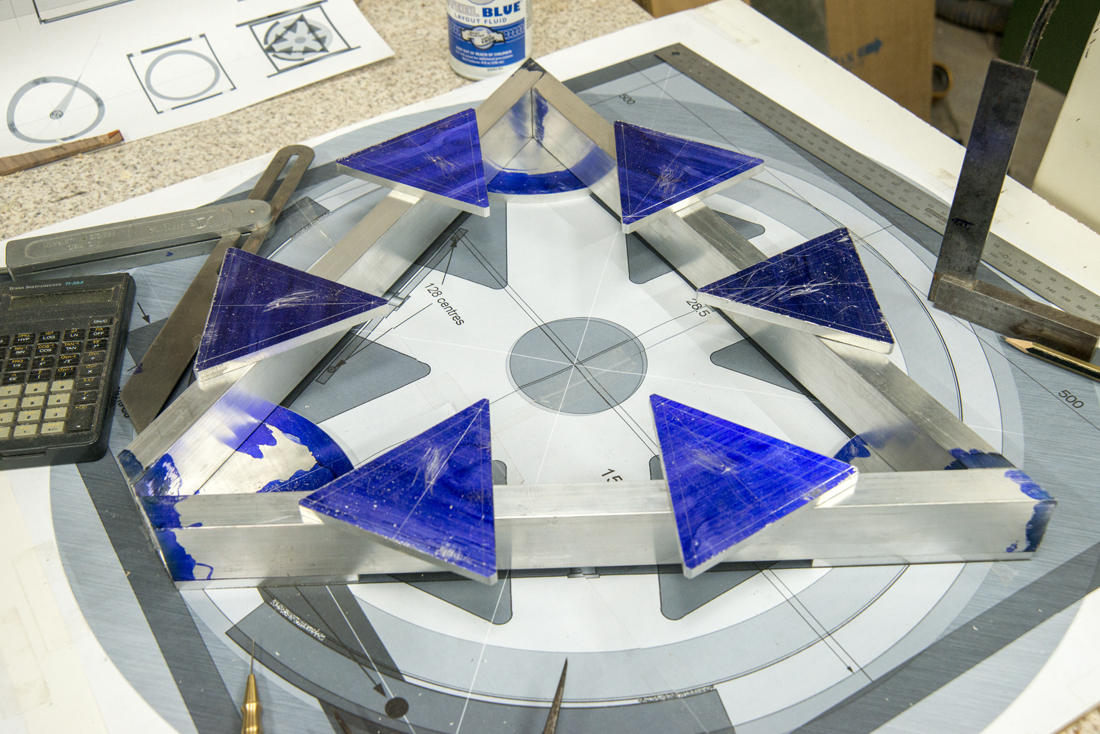
I've already roughed the triangles to shape. I now need to form a domed pocket to their undersides and a flat bottomed counter bore to the upper surface to allow a 2.5mm retaining screw to passs through the triangles, the domed pivot and into the pivot bar. Not shown will be a cap head screw under the innermost support pad, this will act as a retainer for an 'O' ring linking the 6 plates and keeping them aligned.
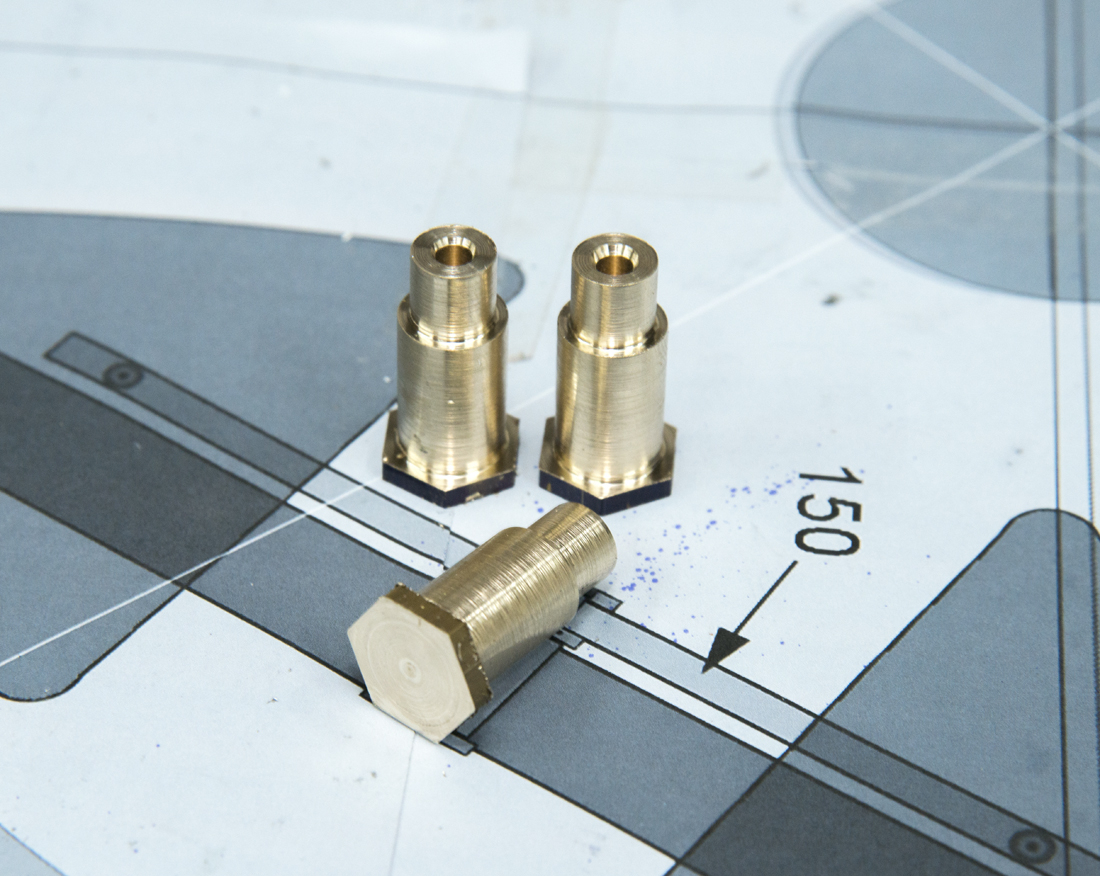
The pivot shaft will be turned from Hexagonal brass leaving a short hex section to act as a bolt head. The shaft will pass through the 1½" x ¾" x 16SWG support beam at 12mm OD, then down to 8mm OD to pass through the pivot bar. There will be a PTFE washer between the support beam and the pivot bar. Then a second PTFE washer and a cap washer and retaining machine screw ties the whole assembly together and allows side pressure to be adjusted so the pivot bar can rotate but not tilt sideways.
That should keep me busy for a while...
-
 1
1
-
-
I like that Peter. I like that a lot.
-
 1
1
-
-
@Piero Thanks for the comments, I like your metalwork pieces you've posted, looks quite robust.
The only 3mm dimmension posted is within the Newt-for-the-web screen grab and that is there purely because the program required a wall thickness for it to run. As this is a truss tube dob there is no solid wall so the 3mm is essentially meaningless. The truss poles are 16 swg or 1.6mm wall thickness and 22.25mm OD which I'm sure you will feel is under sized.
The drawings I've posted have drawn for my reference and are evolving as I flesh out various details in different areas whilst keeping with the overall form of the scope. The upper cage being one area that is currently being fleshed out. I've always intended that the eyepiece will sit at at 45° angle to make life a little easier when viewing at lower angles, and also easier when viewing near the zenith by avoiding having to lean over the scope. They have been drawn that way to keep thing simple thus avoiding having to show a circle as an ellipse etc.
The upper and lower truss pole seats/anchors are based around the use of register pins to avoid location errors and slippage not shown in any of the current drawings..
I've updated the Newt-for-the-web dimmensions sheet to reflect the 75mm secondary changes.
I'll update the build images as things progress
-
I've spent the morning first printing off some of the drawings as A4 sections to build up a full scale drawing which I've taped to an odd board in the workshop. This is where I found suddenly everything is bigger than I thought !!
Then to work on roughing out some of the parts. All will probably need some fine tuning but they're pretty close. I made a decision to increase the size of the gusset plates to allow more fixing at the main frame junctions.
I used a bandsaw to rough cut pieces just over length, then used a disc sander to clean-up back to the lines. Bits get very hot when using a disc sander !!!
Images show the parts cut so far layed out on the plan.
-
 2
2
-
-
-
1 hour ago, CraigT82 said:
What a scope this will be! Great drawings too. 72mm seems small for the secondary, is that right?
It will be 75mm more than fully illuminates any eyepieces I'm likely to use with it. If you look at the Newt for the web screen grab above (top right panel) you'll see with the secondary at 72 mm there's no vignetting. 72mm was the figure that just gave me those results. So with mine at 75mm I have a little cushion.
-
 1
1
-
-
-
@MarkRadice I'll make all the parts with the exception of the mirrors and focuser (Baader Diamond SteelTrack NT)
I've been looking at the secondary mounting and come up with this based on a square aluminium box section, 4 thin spider vanes are clamped to the exterior of the box section using 3mm stainless cap head machine screws with washers and nuts.
There's a fixed plate held inside the box section with an adjustable (tip & tilt) plate. A backing plate just smaller than the mirror is fixed to the tilt plate and the mirror fixed to that with adhesive pads. Not shown: the mirror will have a safety wire(s) to prevent accidental damage should the pads fail.
-
 1
1
-





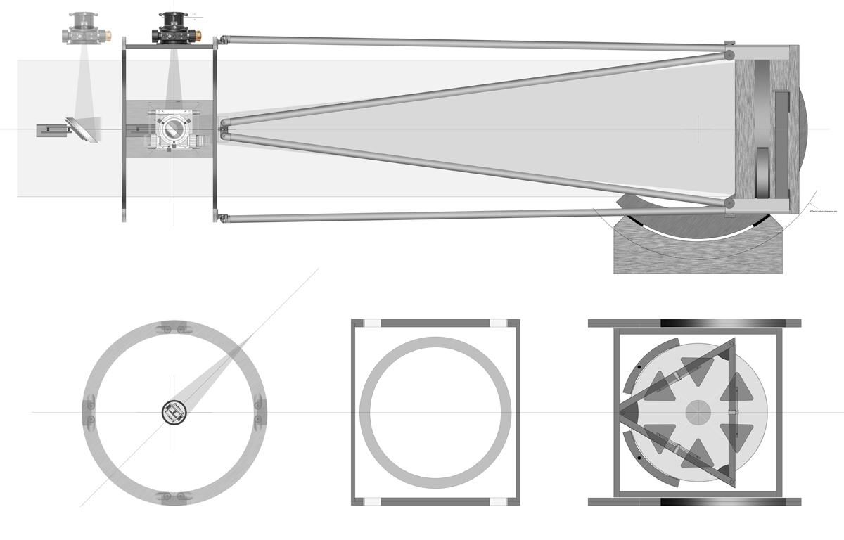



16 inch f5 with Nichol Optics.
in DIY Astronomer
Posted
The mirrors have just arrived and they look beautiful. All packed away again now while I get myself in gear to complete the rest of the scope.😀😀😀👍