


Gina
-
Posts
45,326 -
Joined
-
Last visited
-
Days Won
120
Content Type
Profiles
Forums
Gallery
Events
Blogs
Blog Comments posted by Gina
-
-

Managed to move the hands nearer the clockface and hence the tiny magnets in the ends nearer the Hall sensors and get the clock working but I think there is a future project here to fix the problem properly to provide more reliability.
-
I've come here because after several years of perfect operation and timekeeping this clock has developed a fault following a power cut during the night a few days ago. The Hall sensor that detects the position of the minute hand has become unreliable.
After a power cut or operation of the GMT/BST switch, the clock is run very fast until the hour hand is detected just before the 12 o'clock position with the minute hand at about ten to the hour. At this point the clock slows down allowing time for the minutes Hall sensor to detect the minute hand at the 12 o'clock position. The 12 o'clock position having been found the amount of rotation required to get to the right time is calculated from the time given by the Real Time Clock module. The clock is driven fast until the calculated position is reached and then run at normal rate. The result is that the clock shows the correct time to within a few seconds.
I now need to find out why the minutes Hall sensor is not detecting the minute hand or possibly using another method of detecting when the minute hand is at exactly 12 o'clock.
-
There is no need to run the motor at other than full speed - it isn't that fast - 18v motor running from 13.8v. I don't think acceleration or deceleration are needed either but I'll confirm that when I have the system running with endstop switches. These will be the old Z probes for my 3D printers (been replaced with piezo sensors). They're waterproof, easily mounted and sense any metal at around 4mm. No moving parts (other than the roof) or electrical contacts. They work very well with Arduinos etc. 6-36v supply with NPN open-collector transistor output.
I shall want a couple of push-buttons for local control so that I can use the motor to open or close the roof when in the observatory. I shall also want to mount the rain sensor in a suitable place and connect it to close the roof if it rains.
-
On to the motor drive, I released the clutch on the motor to free the chain, pulled the chain through and connected it temporarily to the east end of the roof with a clamp. The weight of the chain was enough to pull the roof open. Decided to see if freeing the chain from the worm gear motor drive would allow my to close the roof by hand in the event of motor failure (the reason for choosing this special type of garage roof opener motor unit). I opened the roof about half-way, pulled the chain through to take up the slack and then (with the clutch free) pushed the roof closed with the chain going through the motor unit. Found I could do this quite easily. RESULT!
Next I tried power on the motor to see how well it opens the roof. Connected motor to bench PSU set to 13.8v and applied power and (once connected the right way round) the motor opened the roof effortlessly! Maximum current was about 2A and generally around just 1.4A. Test successful!
-
 1
1
-
-
Here is a screenshot of the CAD design for the bracket to attach the chain to the east end of the roof (open end). The circular groove takes the chain which will emerge from the LHS of the groove, down and across to the right giving clearance for the large pulley when the roof is open. A bolt in the vertical hole will hold the chain from pulling out. A 200mm M8 coach bolt through the roof frame and the hole in this bracket will secure it to the framework, with a nut and penny washer to hold both bracket and chain in the groove. The RHS of the bracket is secured to another member of the roof framework to add strength and prevent the bracket turning. This is probably over-engineering but that is me!

-
The NW corner is done and the same as above but I haven't got a photo yet. The east corners will have gate hanging hinges use as peg and loop - at right angles to normal orientation. This shows the idea.
-
1
-
-
My original objective was to make the roof remote controlled and storm-safe when closed remotely but it may not be necessary to go that far as it adds a lot of work. However, I might go a lot of the way towards this and provide anti-lift locking pins at each corner. The drive motor may be strong enough to prevent the roof being blown open. Apart from the roll-off-roof itself there's the opening east end window to consider. I have various ideas for this. However, the main reason for motorised roof closing is from detection of unexpected rain for which I have a rain sensor. With the prevailing wind direction being SW most rain comes from that direction and just closing the roof would be a bit step forward.
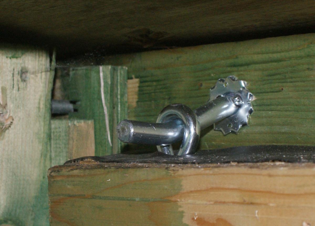
On 09/02/2019 at 18:03, Gina said:If I have pin and ring-bolt locking system (as below) or similar on the four corners of the roof, that engage when the roof is closed, I will only be necessary to lock the roof closed so that pin and eye stay engaged.
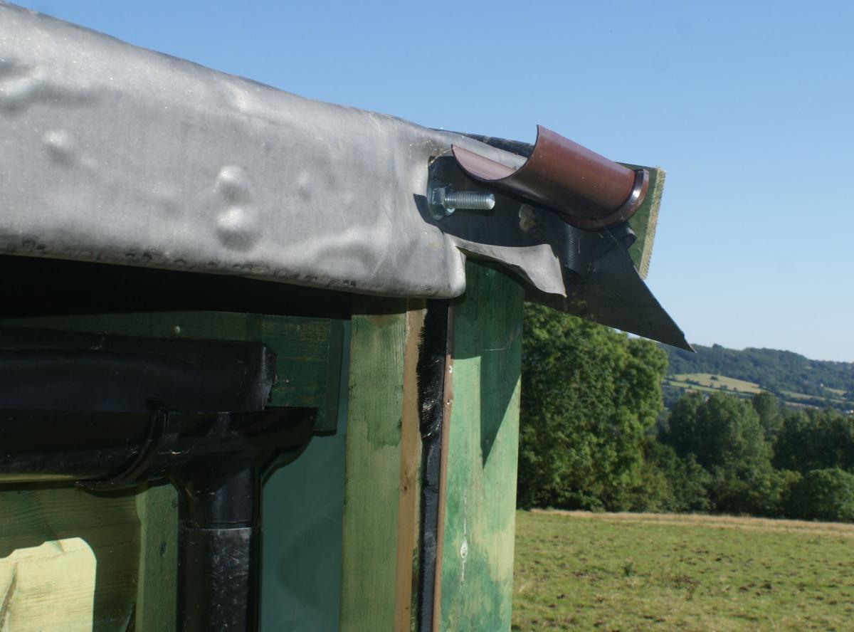
These photos show the pin and ring-bolt locking system on the SW corner of the roof. The pin is in the west end beam of the roof and the ring-bolt in the partition framework between scope room and warm room. The 3rd photo shows the end of the pin bolt on the outside of the ROR, which is in the open position for this view. These are farm gate fittings and very strong. I can do exactly the same on the NW corner which is just a mirror image. The east end corners will need looking at. The SE corner did have a peg which went into a hole in the frame but the hole has broken out and will no longer work.
-
On 04/02/2015 at 15:53, Gina said:
Gradually getting there
Motor assembly now mounted in the observatory. I have also coupled up the chain in the motor with the chain in the observatory making a total of three lengths of bicycle chain. It is too long and I shall be taking off nearly a metre once I've confirmed the exact length required.
Here are a couple of photos. The chain runs well with good alignment round the large (black) pulley, through the motor unit and round the small (green) pulley. I have yet to screw a spacing block to the ROR carriage and the chain is just parked over a bolt and hence out of alignment from the small pulley. However, in spite of that I was able to check that the chain ran through the motor unit freely enough to manually open or close the roof without power, with the clutch disengaged - something I was a bit unsure about.
-
On 03/02/2015 at 21:55, Gina said:
Motor unit and small pulley now mounted on base. Designed and printed inner pieces to go inside the ball bearing to space the pulley away from the wood and provide a larger area to take the pressure and the size of a 70mm x 5mm wood screw, used to fasten the pulley to the 50mm thick wooden base. A penny washer was used under the screw head to spread the load and avoid possibility of splitting the ABS plastic.
Here is a screenshot of the SketchUp model of the two bearing inners.
Here is the small pulley mounted on the wooden base.
To fasten the motor unit to the base I drilled holes through the plastic casing and attached it with wood screws, again 70mm x 5mm diameter.
-
1
-
-
On 03/02/2015 at 18:10, Gina said:
A bit more progress with photos.
The large pulley and chain.
This shows whee the chain emerges from the large pulley. Used to work out alignment of drive motor.
Drive motor placed on mounting board with chain placed in approxinate position.
-
These pictures show the previous running track which has since been replaced by heavy duty galvanised iron sliding gate track from FH Brundell.
-
The large pulley was attached to the partition wall frame of the observatory with a long bolt and covered by a 3D printed cover to keep the wet off as part of it would be outside the protection of the observatory wall.
On 03/02/2015 at 16:16, Gina said:I now have the large chain pulley finished and equipped with ball bearing with spacers and hub to fit between the sides of the cover.
Some photos...
Pulley, chain and cover with the bearing just visible.
Fitted into the observatory and bolted to the framework with rubber seals fitted above and below chain cover.
Outside view of the chain cover. The brush type weather excluder could do with moving over to the right a bit to reduce the bristle bending. Might leave that until it's a bit warmer. A mere 2C here this afternoon and windy with it
-
As the diagrams show, apart from the motor unit, chain and brackets to attach the chain ends to the roof, two sprockets or pulleys are needed - a small one and a large one. I had some black ABS circular blanks some 150mm diameter x 22mm thick and decided to machine one of these in my lathe to make the large pulley. The smaller one I 3D printed.
On 31/01/2015 at 12:12, Gina said:Large pulley turned to shape for chain and ball bearing.
-
1
-
-
The roof will be pulled open and closed using bicycle chain and a garage door opener. Since it is essential to be able to close the roof manually if the motor drive should fail, I needed a way to disengage the drive from the roof. The easiest solution to this was a motor unit with a clutch whereby the chain could be free to be pulled through with little resistance. These were seemingly unavailable in the UK or extremely expensive but the late Per Frejval offered to get me one and send to me from Sweden. (Oh how we miss dear Per!!) Being able to feed the chain through the motor unit without having to run the motor would also be a great help in setting up.
This quote form earlier shows the rear of the motor unit where the chain runs (top groove). The clutch mechanism can be seen - a simple dog clutch, which when disengaged leaves the sprocket free to rotate. Testing showed that it was easy to pull the chain through or indeed to push it through initially.
On 22/01/2015 at 14:43, Gina said:I now have the motor to drive the chain for the ROR. I plan to use this with the motor in the case with chain guide. Here's a photo showing the drive sprocket and chain guide.
And here is a diagram of how I think I can arrange the chain drive for the roof - chain shown in red.
On 04/02/2015 at 22:02, Gina said:Schematic showing the roof open and motor drive parts.
-
I'll start with some photos of the observatory taken a few years ago. From the north looking roughly south and then from the south at various angles.
On 16/05/2015 at 23:24, Gina said:With the lovely sunny weather today I hopped over the electric fences into my neighbour's field and took some more photos of the south side and ends of my observatory, showing the new east wall flap/window. It's now ready for connecting up the motor for remote/automatic control.
-
4
-
-
This printer has now printed it's last, having been superseded by a bigger and better printer. Some time I will get round to dismantling it. I has served it's purpose pretty well.
-
I keep adding bits as I find the information. I use KStars as client - free Open Source software, multi-platform so works on Windows and Mac OS etc. as well as Linux.
-
Replaced connector for RH XY motor and now that motor is working. I now have the X and Y homing working fine but having a problem with the Z which is probably something wrong in the homez.g and homeall.g code.
-
A connector got pulled off one of the motor cables whilst moving thing around and I seem to have mislaid the metal bits that go inside to make up a new one. Meanwhile, I've been testing as far as I've got. The following items tested and working.
- Hotend heater
- Heatbreak cooling fan
- Bed heater
- RH XY motor
- X endstop
- Y endstop
- Z drives
-
The Z axis is driven by two NEMA23 stepper motors (as shown in a diagram in a previous post) which go below the base of the printer. To allow for these the printer is supported by four castor wheels which also make moving the printer easy.
Here is a photo of the current stage of build. Not finished yet and needs some cables connected and everything tidying up. The blue cylindrical part in the bottom centre takes the filament reel, with the filament being carried in a PTFE tube up to the extruder. Between extruder and hotend is a new improved version of the Precision Piezo piezoelectric probe that works by sensing a light touch of the print bed against the nozzle when Z homing. My attempts at using the bare piezoelectric disc and amplifier were less than totally successful - I'm hoping this will be more reliable, the design certainly looks much better.
-
Decided that buying cut-to-size plywood was both expensive and not guaranteed to be exactly what I want and also preferred to use what I had so decided to buy a good quality circular saw and fine cut blade and do it myself. The saw will have plenty of other uses too. I was able to cut the box panels down to exactly the size I wanted and rebuild the box. Everything had turned out to be precisely to size and I have been rebuilding the printer. It is now almost complete and ready to work - just need to replace a connector on one of the motor cables.
Some diagrams and photos. Firstly, top view diagram of the printer box and bed.
This is a cross-section of the bed. Top is a borosilicate glass build plate, then silicone heater pad (not shown) followed by 12mm thick PU for insulation and to ensure good contact between heater and glass. This is supported by a 6mm thick plywood panel and the whole lot held together with 3D printed framing.
Here is a photo of the bed assembly. The plywood bed base is bolted onto two rails of aluminium extrusion. Between these rails are two more which will be attached to the Z drive units.
Here is one of the Z drive units (C-Beam with gantry plate, wheels and trapezoidal screw system) with a piece of extrusion attached to the gantry plate.
Here is the partly assembled printer, showing the box, X and Y rails and Z drive units at the sides.
-
The print bed will be from previous Giant printers - 500mm x 500mm x 5mm aluminium plate with mains voltage silicone heater pad underneath. I want to make this latest version of the printer capable of covering the whole of the print bed if possible. The bed will be supported by a plywood sheet itself supported by an aluminium extrusion frame attached to the C-Beam double gantry plates. Between bed and plywood I plan to have 12mm thick PU foam for insulation and to ensure the heater pad is touching the aluminium plate (the glue has given up in the central region). The C-Beam will be 1000mm giving a printing height of just over 800mm. NEMA23 stepper motors will provide the drive.
Amazingly, I have found a PEI sheet big enough for my Giant print bed :- PrimaFil PEI Ultem sheet 500x500mm-0.2 mm and with the pound dropping fast against the Euro I've decided to get it now. It can go on the aluminium print bed to provide a better printing surface than plain aluminium while cutting out the glass plate will greatly reduce the weight.
-
No, not found the lens or any part of it.
-
This printer has been superseded and now dismantled with parts used in replacement printer called "GinaRep Concorde".


 Motor assembly now mounted in the observatory. I have also coupled up the chain in the motor with the chain in the observatory making a total of three lengths of bicycle chain. It is too long and I shall be taking off nearly a metre once I've confirmed the exact length required.


Observatory Roll-Off-Roof Automation
in Astro Projects
A blog by Gina in General
Posted · Edited by Gina
The motor drive for the roof is proceeding but meanwhile I have been giving more thought to the fold-down east window. How I know the consensus of opinion on this sort of thing is to have the end flap mechanically connected to the main roof so that opening the roof opens the flap and vice versa. However, with the two currently independent and both manually operated, I find I often like to have the window/flap open with the roof closed. I have also found that having the window pivoted along the bottom has not worked as well as expected. One problem is that the window frame is not very stiff. Also, I have had to put the downpipe for the ROR guttering back to the south side and would be in the way of a traditional mechanical connection between roof and flap. All this has led me to thinking again about the best way of opening and closing the window.