


Gina
-
Posts
45,326 -
Joined
-
Last visited
-
Days Won
120
Content Type
Profiles
Forums
Gallery
Events
Blogs
Blog Comments posted by Gina
-
-

Having another look at this project. The impasse ATM is the escapement. To date I have not been able to produce an accurate enough escape wheel. I've worked out that the tolerance required is of the order of 0.1mm and have found this difficult to achieve in a 3D printer. I may have another attempt with my latest 3D printer. The problem is that if the teeth are not all exactly the same distance from the centre of rotation and the same shape, the drive is either insufficient to keep the pendulum swinging or the escapement "skips".
One "fudge" I've thought of is to drive the pendulum separately so that the escapement is not required to drive it. This would mean a far lighter weight would be needed to run the gear train with less tendency to "skip". Of course, the pendulum would need to be "tuned" fairly accurately to the 2s period of the drive or the two would "fight". Effectively, the pendulum is a very high Q tuned circuit, albeit a mechanical one. Apart from getting round the escapement problem, the clock would effectively be a "slave" to the RTC module and stepper motor driver circuit. I had planned to add an automatic time-keeping system whereby the pendulum length was adjusted to make the clock keep time. A closed loop control system. The open loop pendulum drive would be simpler.
I want to get the time-piece part of the clock working so that I can get on with the striking mechanism which intrigues me.
-
Drat changing the clocks - it's upset my Moon Dial Clock. I have a switch on the top which determines GMT or BST and when operated restarts the clock as well as determining whether to add an hour for BST. Flipped it this morning for the clock change and the hands sensors are not working. Have to switch it off and make sure the hands are as close to the face as possible. As I said above, this could do with a design change to make it more reliable.
The position of the hands is detected by small magnets in the ends of the hands and Hall devices built into the clock face. I was thinking the minutes shaft went through to the back of the clock but it doesn't - its the seconds shaft - the minutes is a sleeve like the hours but longer. The sleeves only go back as far as the relevant wheel/gear. All this seemed a good idea at the time and avoids the standard clock slipping clutch which is the standard way of setting the time and seemed difficult to implement in a plastic geared clock. Also, the ability to set the time automatically was a nice extra.
I really don't want to completely redesign and rebuild this clock. Maybe see if I can use bigger magnets.
-
The lights dim when I run the mains heater on my Giant printer 🤣 Well, not quite but it is 1.2KW which is more than a bar of an electric fire.
Having tried PEI sheet on my Concorde printer with unsatisfactory results, I'm now not sure about using it on the bed of my Giant printer. I didn't do very well with plain aluminium for print adhesion though and unless I can adjust print settings to make plain aluminium work I shall definitely try the PEI.
-
 1
1
-
-
Photos of finished observatory and HERE (Posted May 16, 2015 ).
-

-
New power distribution box.
-
1
-
-
A decent lunar image.
On 15/04/2014 at 23:18, Gina said:A lovely clear night with very nearly full moon. Got problems with the EQ8 mount though
Gross slewing errors - won't go away and then back to same place. Set up on the moon for rough focus and mount position then tried to find M51. Used CdC to slew to it but it wasn't in the FOV so I checked slewing back to the moon and it was miles off! Several degrees in fact - I could see by eye that the scope wasn't pointing at the moon. Have to see if I can do anything with it in the daytime tomorrow. Meanwhile here's one of the images I took of the moon - for what it's worth. 0.1s exposure with 5nm Ha filter.
The MN190 scope and EQ8 mount.
On 16/04/2014 at 20:49, Gina said:I does seem that there's a frirmware upgrade that would help - it reduces the maximum speed of slewing a bit and reduces the acceleration and deceleration on starting and stopping. This should help prevent clutch slippage and stop the grating noise I'm getting with max speed slewing at one point.
I spent most of the afternoon playing around with the mount and I believe I've got it sorted out
I think the reason for not returning to the same position was slipping clutches. I took everything off the mount including the weight and tried it out with no load. It seemed to slew in all directions fine. Checking the clutches I found that even with the levers all the way over to the hold position I could still move the mount by hand. So I undid the screws that hold the levers onto the shafts and reset the positions so that the clutches only just slipped with the levers in the off position. Now when tightened all the way up it's a lot harder to move the mount though I think this could be better. This is an aspect of the EQ8 that I don't much like. The levers are awkward to get at and hard to turn with fingers - they could do with being longer.
I then remounted the MN190 and adjusted the balance. Had to rearrange the filter wheel and guide camera as it was catching on the mount. When I was setting up the mount I only had the MN190 on it for a short time and was having problems. I used the Esprit 80ED for setting up PA and not really quite finished when the weather turned bad. Anyway, I have checked slewing the scope into various positions and tied the cables out of the way of moving parts. There is some grating noise when slewing at full speed in one direction near the Home position but otherwise the noise is normal.
There is some wispy cloud about but I'm going out shortly to see if I can manage some imaging tonight.
-
Found some pics in another thread.
On 10/01/2014 at 12:58, Gina said:Here are some pics that show the foundations. The last one shows a possible access point.
Just taken some photos by putting my camera under the floor using the gap shown above. This is the best one.
I'm going to try to get the pump in through here to the lowest place just in front of the pier and run the outlet out the other side and up over the bank and into the field.
As can be seen water does drain away and most of the time there is no problem - normal rain water just drains away through the ground. It's when we have torrential downpours that the foundations flood and we seem to be getting more and more of these.
-
I had help with the 5m long cladding - two SGL members 😀
On 13/11/2011 at 20:19, yesyes said:Here is a nice group picture of the crew after we had mission accomplished. 😉
-
Ah!! One clear photo amongst dozens!!
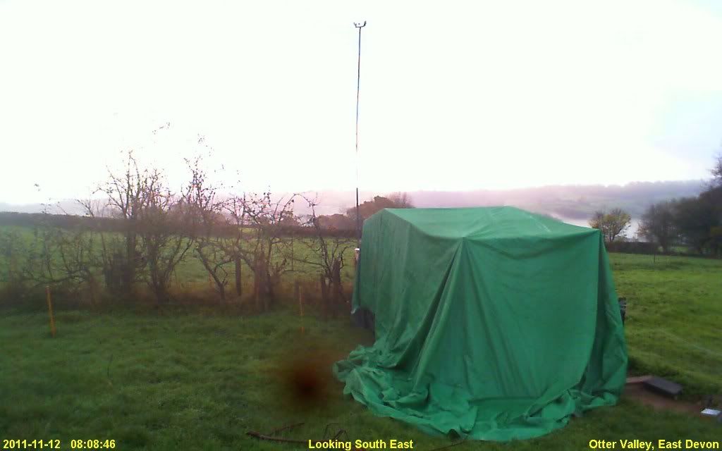
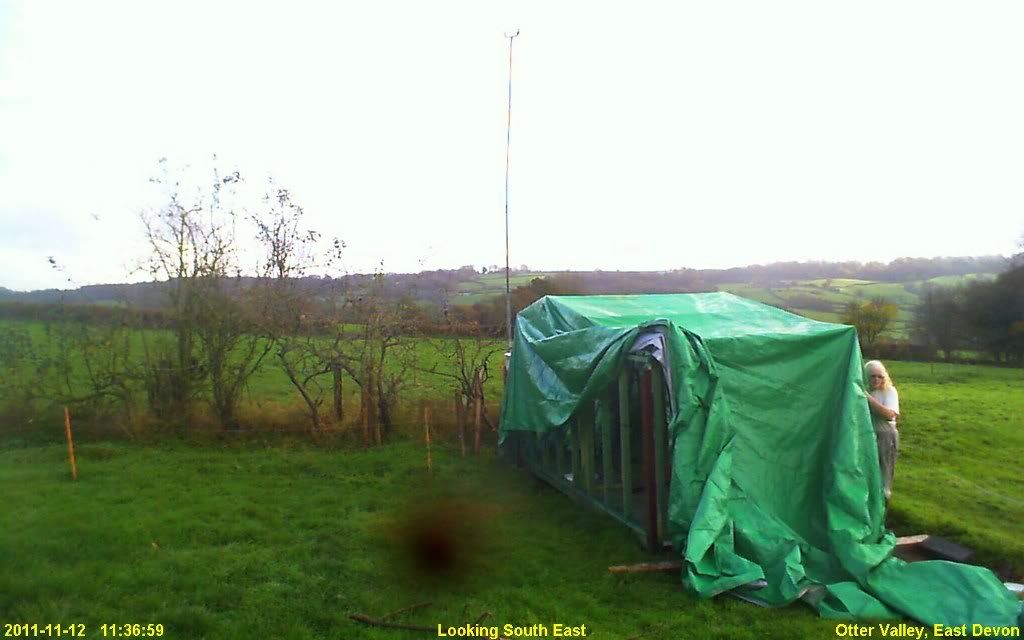
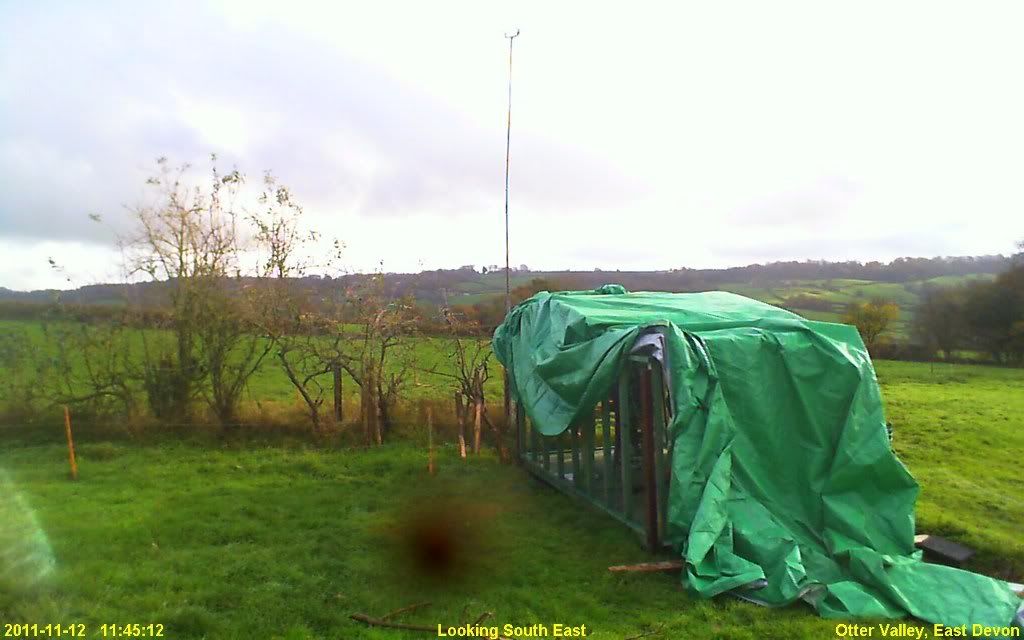
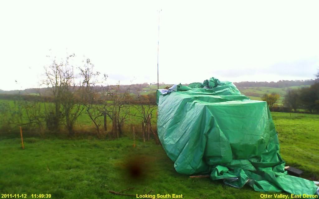
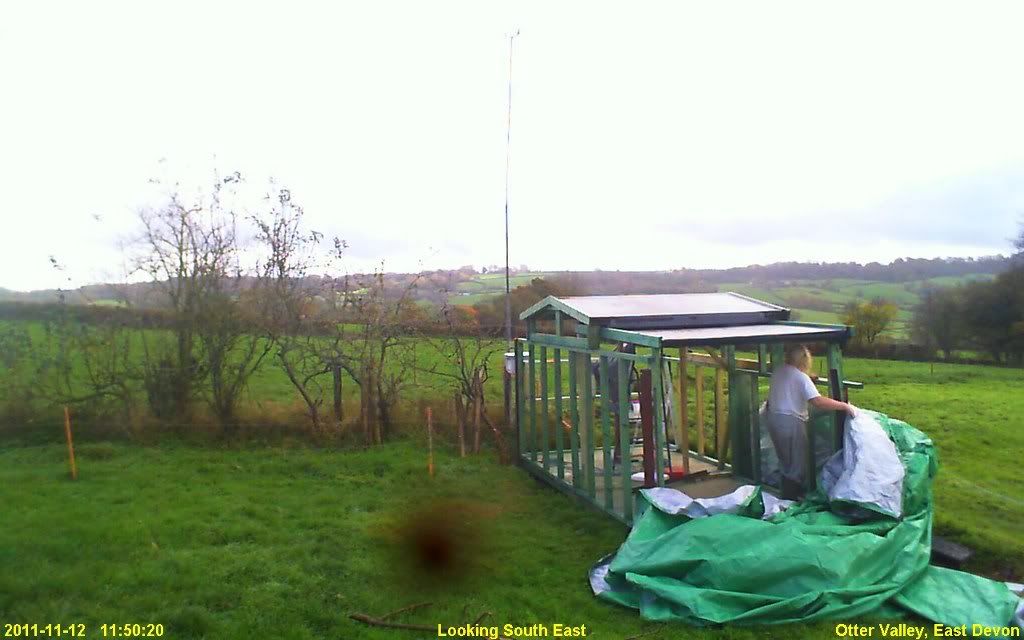
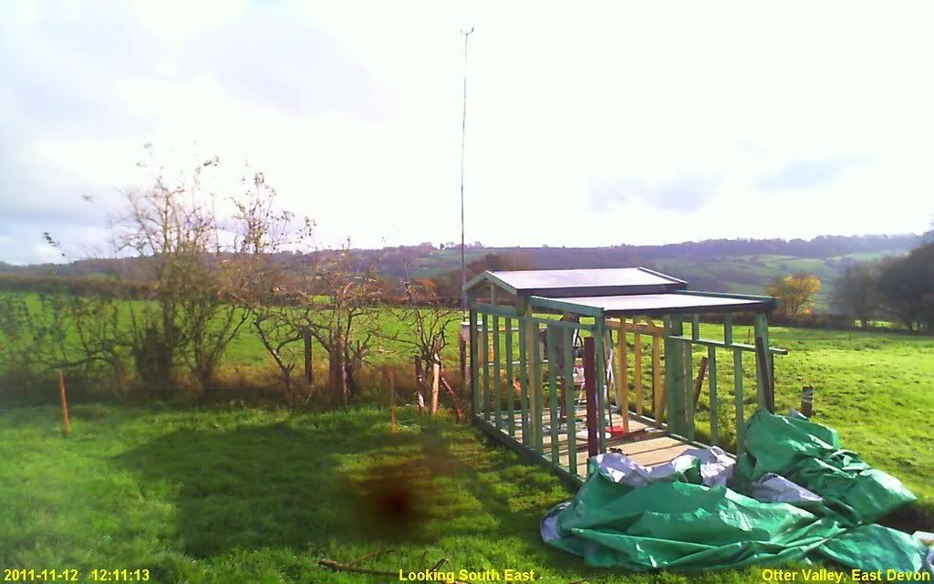
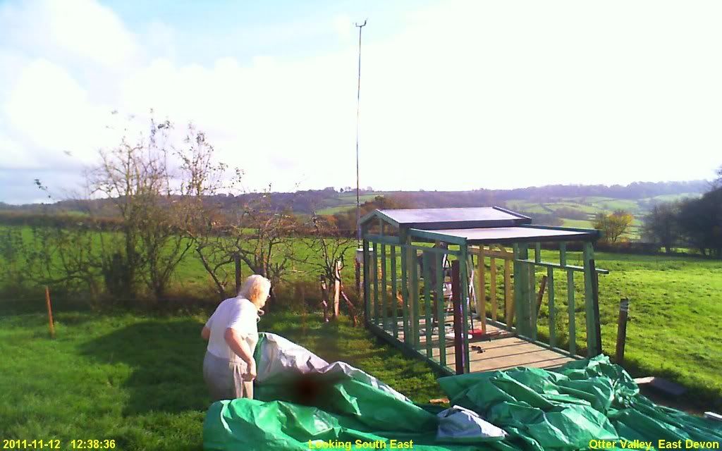
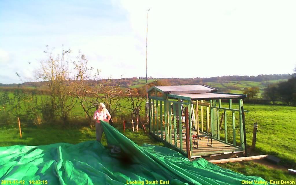
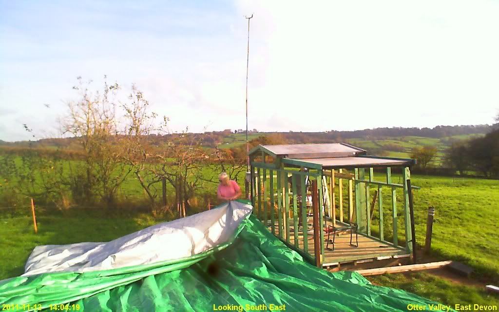
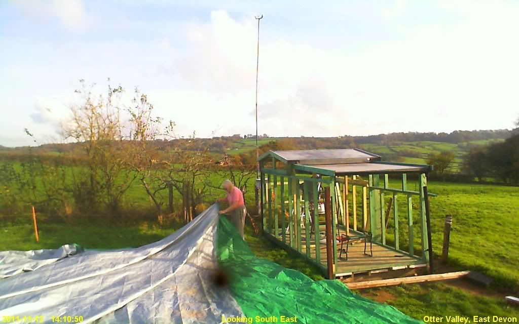
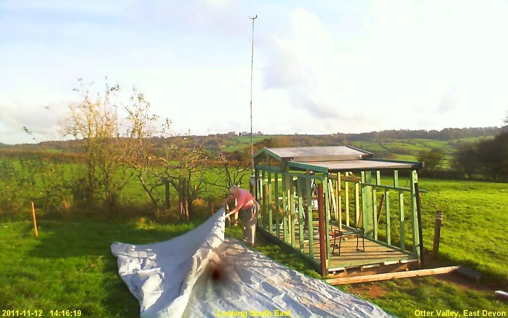
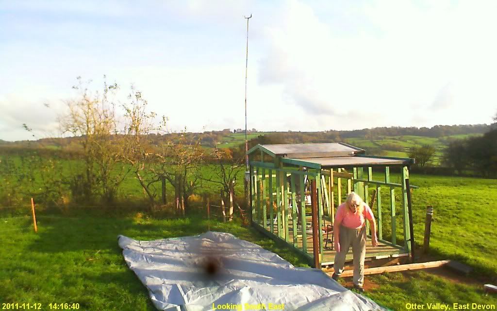
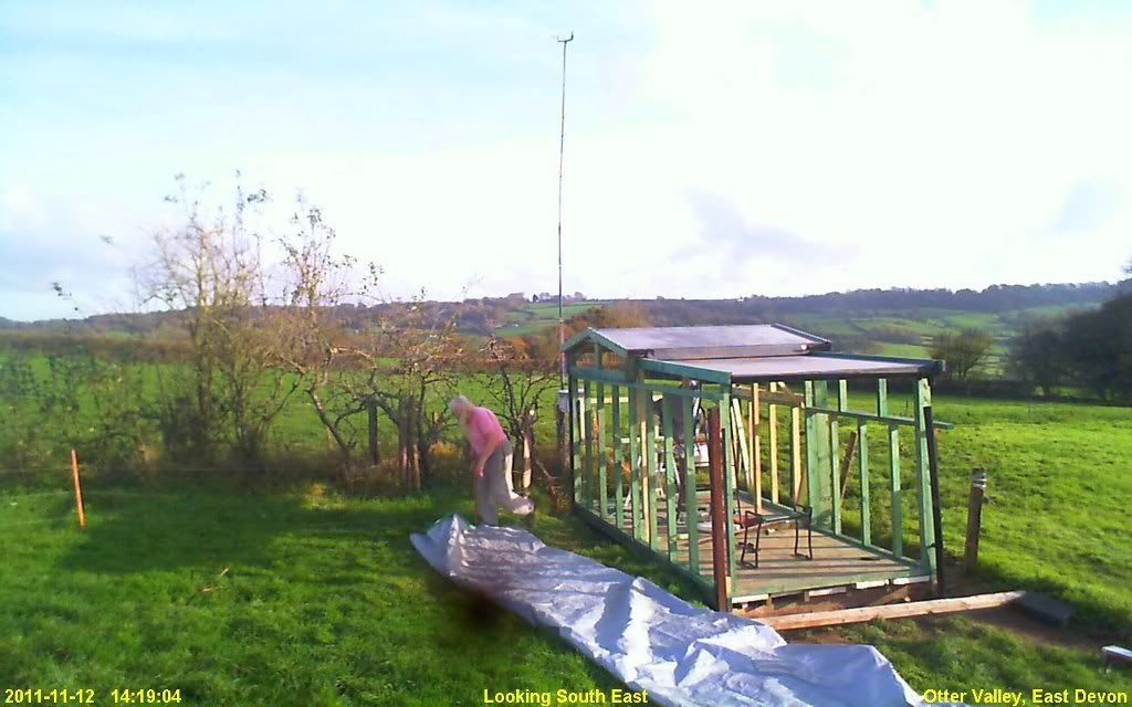
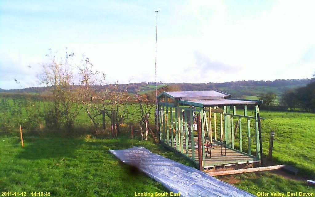
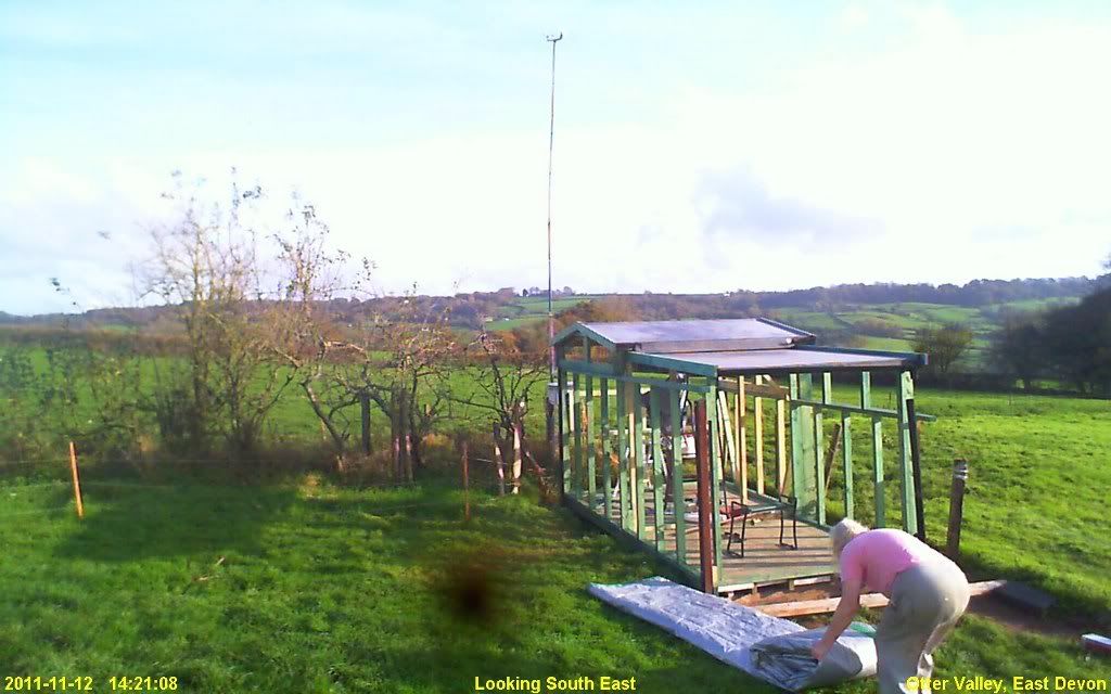
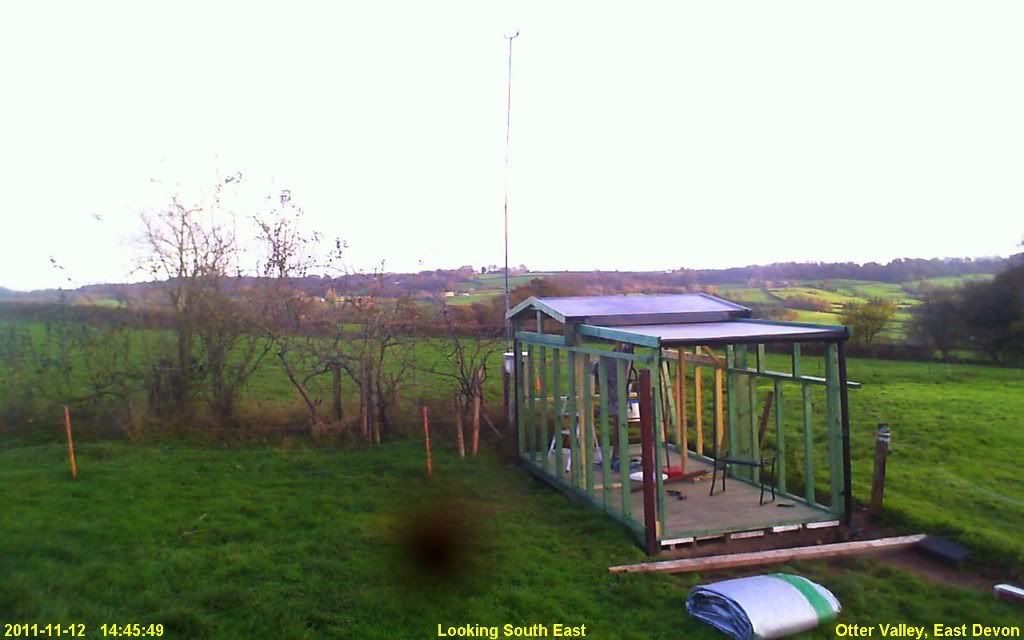
On 12/11/2011 at 20:55, Gina said:Fine weather today with a light breeze and very mild. Several hours of sunshine
However, with yesterday's heavy ran and a heavy dew everything not covered up was dripping with water. Also yesterday's rain had formed large puddles in the tarp and these took quite a lot of lifting and pouring away. The weight of water holding the tarp down under the floor made it difficult to pull clear. I think it would have withstood a gale without being fastened down!
So some time was taken up getting the tarp off the building. Yet more time was taken up folding it up for stowing away! That was today's activity on the obsy build. Other time was needed to go out and get goat feed. So no actual build progress today.
Just webcam images today of removing tarp and folding it up. The first pic shows a large puddle at the front of the tarp as seen from the webcam.
-
On 03/10/2011 at 21:18, Gina said:
Thanks Glen
Just realised... I do have some pics of the work today - the webcam saved image files
So here's part of one saved at 17:30.
OH NO!!! Looks like I started hosting my individual webcam images on photobucket!!!
 On 22/10/2011 at 20:22, Gina said:
I've ordered the shiplap - at last. Just sufficient funds now. 40 lengths of 4.8m by 136mm coverage per board. Cost just over £360 inc VAT.
Another fine but cold day with a chilling breeze. No major milestones passed today on the actual build - just a number of small, tidying up jobs.
1. Trimmed the excess rubber membrane from the warm room roof.
2. Lifted end floorboard from warm room floor and trimmed it to width.
3. Applied wood preserver to freshly exposed wood on edge of floorboard.
4. Applied wood preserver to various other pieces.
5. Several little jobs.
Didn't take any DSLR photos so I've cropped some of the webcam saved images and uploaded those.
-
Looks like I've still got the odd good photo 😀 Maybe I'll have enough - I don't need a full "blow-by-blow" account of the build!
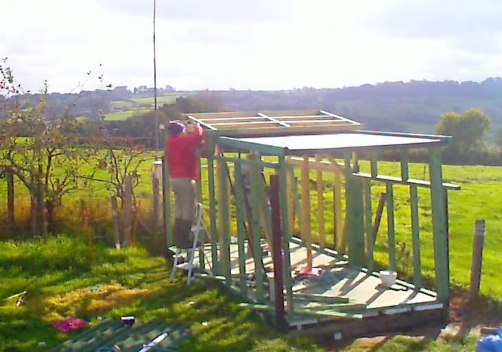
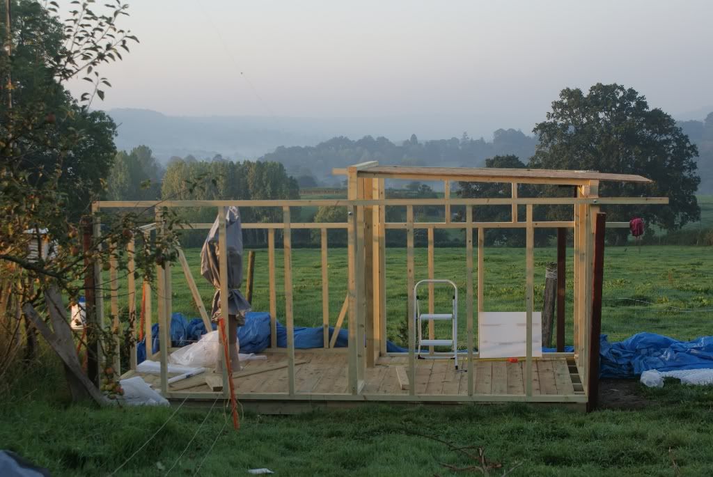
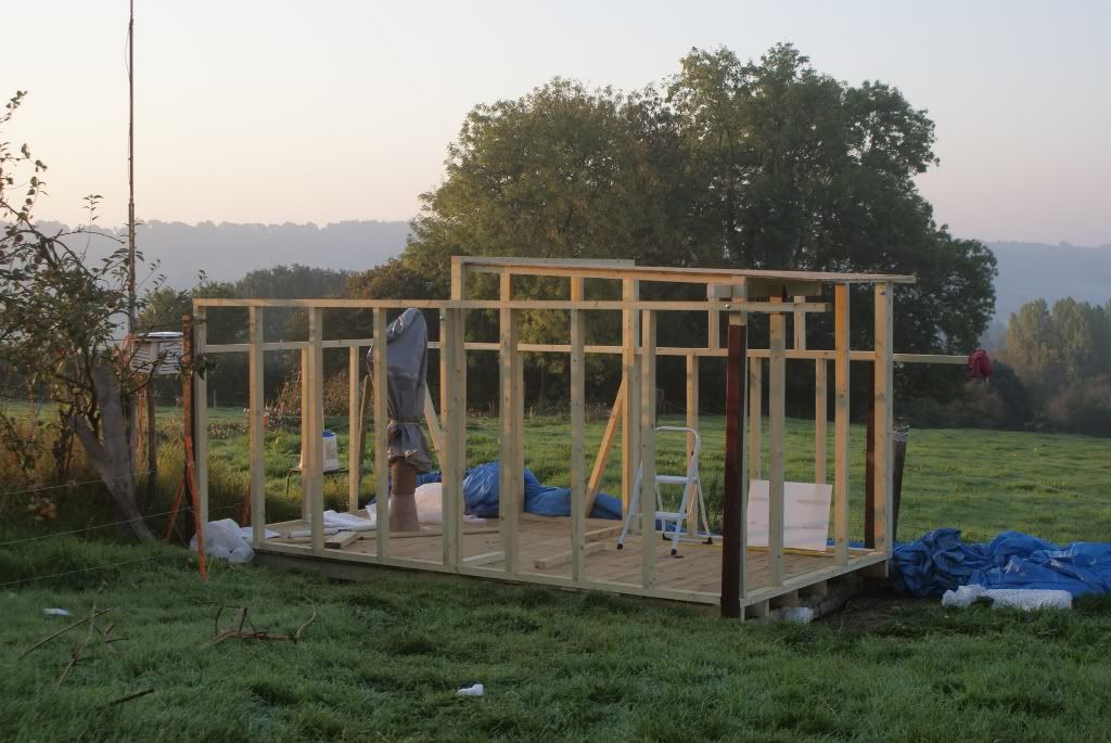
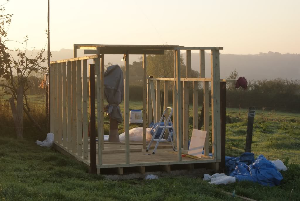
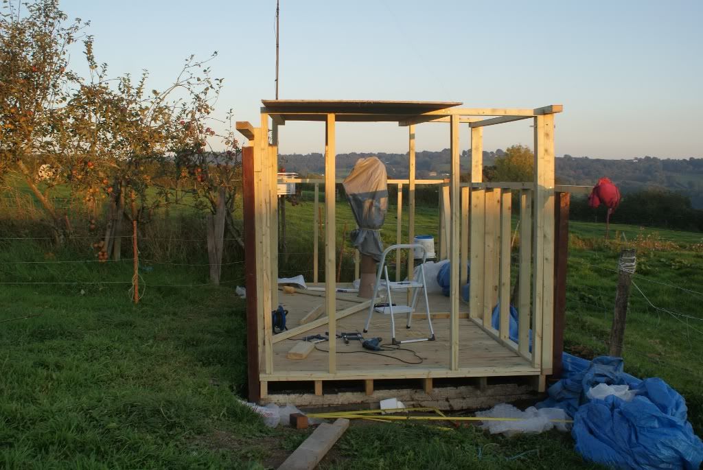
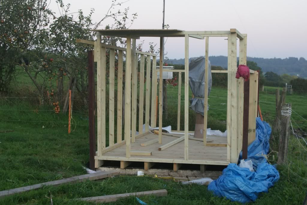
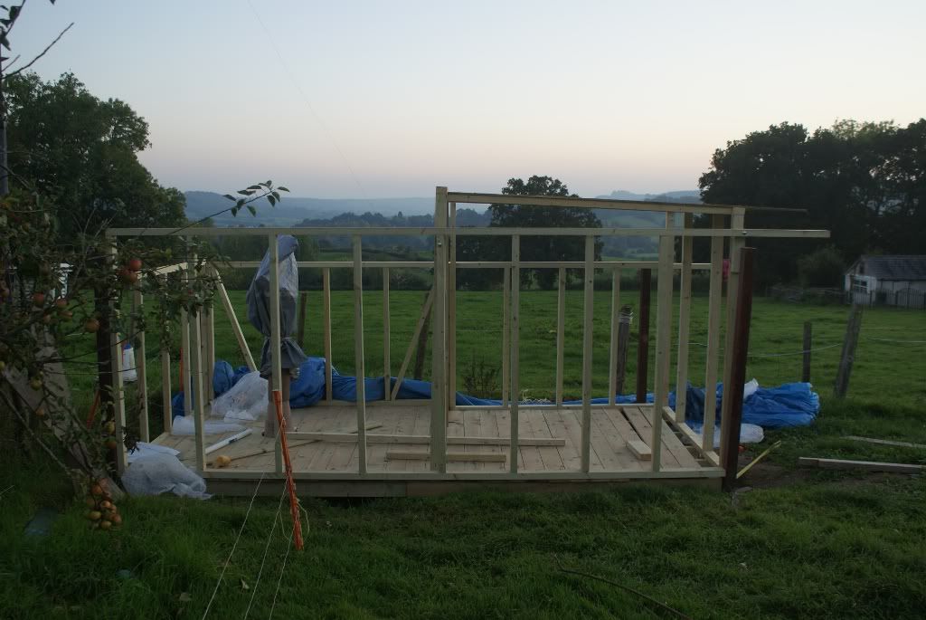
On 30/09/2011 at 08:53, Gina said:As promised - photos from yesterday's progress, taken in the early morning sunllight earlier today.
-
Grumble, grumble, grumble. Now I know where most of my decent build photos have gone. Just have to use a few webcam shots I guess, and apologise for the poor quality.
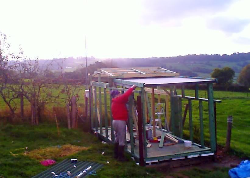
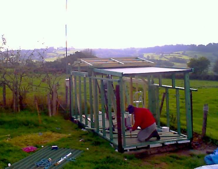
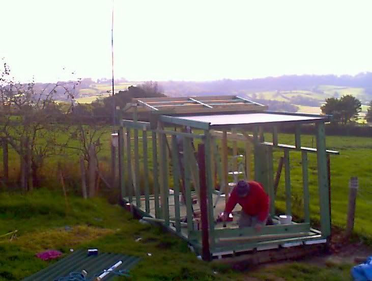
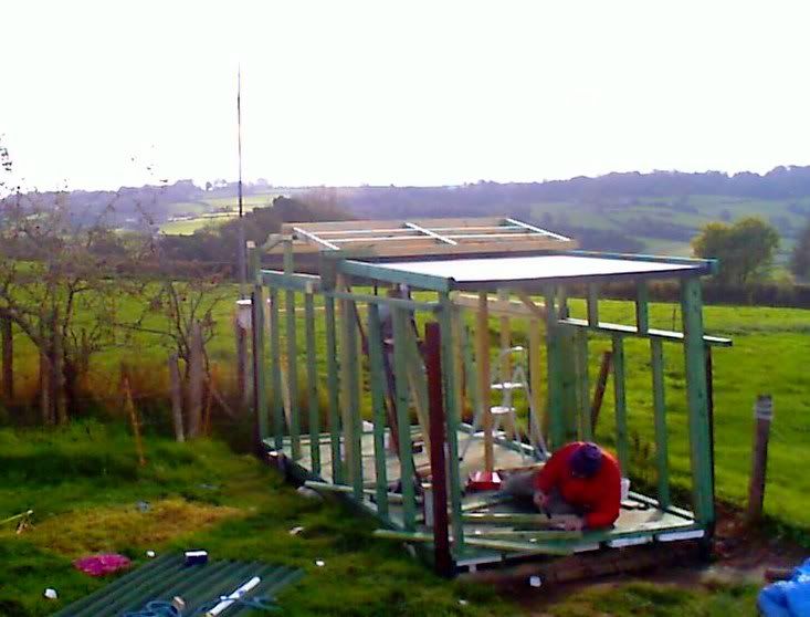
On 28/09/2011 at 21:33, Gina said:Good weather today - fine and sunny with a light breeze - enabled me to make some more progress. As usual, not quite as much as I had hoped but it's coming along quite nicely.
With a very heavy dew this morning, I left the tarp on until it had dried off. Meanwhile, inside the "tent", I screwed some frameworks together ready to be erected later.
So here is a list of progress today :-
1. Finished screwing the warm room south wall frame together - well the bottom part - still have the window frame to do. The side pieces also provide extra support to the top rail which supports the roof.
2. Main structure of the warm room west (end) wall frame prepared and screwed together.
3. Most of the warm roof roof frame cut to size and screwed in place.
4. One 8x4 OSB sheet placed in position to check supporting framework.
5. Various odds and ends including bottom of middle wall, and drilling and bolting sections together with 10mm coach bolts, nuts and washers.
Finally, a section taken from the webcam which provides a different angle of view, difficult to take from ground level.
-
I had to buy a large tarpaulin!
On 19/09/2011 at 18:50, Gina said:Today's progress!!
On 21/09/2011 at 19:37, Gina said:Thought it was going to stay fine... NOT!!
So I've had to put the tarp back on for overnight. It's properly on now and roped down but here I am starting to haul it over the top at 7pm this evening
On 22/09/2011 at 20:15, Gina said:Very nice
Missed out on the morning for continuing the build but at least I bought some things towards it
Today's activities towards the build :-
1. Further adjustments to the pier hole in the floorboards.
2. Dividing wall frame (currently held in place with clamps).
3. Some wood cut for the warm room south wall.
No DSLR photos ATM - I'll take some tomorrow - but here's a section of the webcam image.
-
Good job I didn't host the webcam pics that way!
On 19/09/2011 at 08:56, Gina said:Right... Now posting build updates in this thread
Well, it started off fine this morning but we've had a heavy shower and the forecast is for more of them
I have managed to cut some more floorboards and put them on the joists temporarily. Here is part of the webcam image.
-
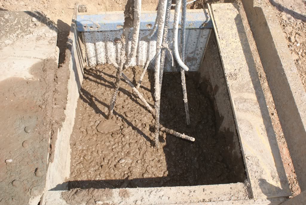
Pouring the pier and block - photos ruined by PhotoBucket. I shall never never rely on a photo hosting service to host my photos!!
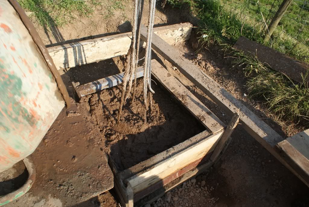
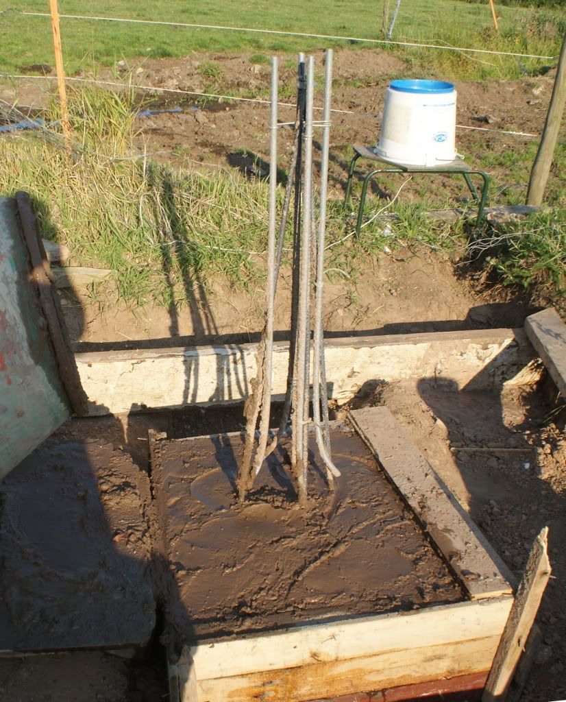
On 17/09/2011 at 18:20, Gina said:The following set of photos show the filling of the base of the pier.
-
Found some in another thread.
On 30/09/2011 at 08:53, Gina said:As promised - photos from yesterday's progress, taken in the early morning sunllight earlier today.
-
This is when the observatory was almost finished apart from the internal fittings. I know I had some good photos of building all the framework. I'll search the SGL archives again!! This is the end of this build thread.
On 16/11/2011 at 09:25, Gina said:Nearly got to the stage of doing the outer door on my obsy build and considering how to hang it.
Two possibilities :-
1. Hung on the RHS (see pic attached) and opening outwards. This would mean a slightly lower doorway (about 5'7") to clear the guttering.
2. Hung on LHS and opening inwards. Doorway headroom now limited by guttering at about an inch or so higher (about 5'8").
I think the advantages of the door opening outwards outweigh the additional headroom through the doorway but your opinions are welcome.
-
I modelled the observatory on the computer (in SketchUp) which I might mention - not sure.
On 27/09/2011 at 21:55, Gina said:I haven't completed the modelling but this should give an idea of what I have in mind :-
-
On 15/09/2011 at 16:03, yesyes said:
Looks like one of your goats has decided that the joists should not run parallel..
They are sooo cute...
Thought I had DSLR photos of the build but can't find them ATM. These are webcam pictures. I had a live webcam running as I was building the observatory for members her to watch on my website.
On 26/09/2011 at 14:28, yesyes said:Looks like one of your goats is fed up with the lush grass and prefers foil now...
On 01/10/2011 at 12:53, pritc said:Gina,
Get your goat to hold the screws for you.......
Wayne
-
There seem to be some photos missing and some that were hosted on PhotoBucket have been blurred and a horrible PhotoBucket emblem added totally ruining the image.
On 13/09/2011 at 11:34, Gina said:OK, will do. The webcam is live though.
The view that the design often has to change as the build progresses has been borne out with the joists. The timber I've just bought is a bit more flexible than the second hand stuff of the same dimensions that I used for testing. So I've moved one of the joists that was over the pier base block to clear the block and inserted an extra joist from near to the block to the end of the warm room, with a cross piece (noggin) at the block end. This in turn reduces the separation under the warm room and outside of the block in the main standing area of the obsy.
Also, the floorboards that were supposed to be 25mm (1") thick, aren't. I guess 25mm was the sawn size and the planed size is a bit less. Floorboards are PTG - planed, tongued and grooved. So closer joists are wanted to get the same flexure. Timber sizes tend to be approximate anyway - I allowed for this by increasing the number of lengths I ordered above the calculated minimum. Better one too many than one too few.
-
This shows the very first images I took with my first telescope on the new pier. This also shows the magnification the telescope gives compared with an ordinary camera as shown in the previous quote. Could be worth including.
On 23/07/2011 at 15:24, Gina said:Taken a couple of terrestrial images with scope and DSLR. Tried to do some solar but the clouds keep getting in the way. The sunny spells are too brief
Must say the scope and camera feel very much more stable on the pier
I can focus without moving the image. And these images were taken without camera remote release.
Images attached :-
1. Unmodified image of tree.
2. Image enhanced in GIMP.
3. Image of comms tower on far hill.
4. As above but enhanced.
-
On 23/07/2011 at 13:45, Gina said:
Put my little scope on the mount and tried various alignments. At the same time measured up the wall height to give clearance of view. Placed a short piece of floor board on the joists to get the floor height (roughly because the floor board I used was thinner than the ones I'm getting). BTW, I jumped up and down on that board and it only moved a little
Some photos :-
1. Scope aimed at distant test tree and almost exactly horizontal. The southern horizon is a few degrees above this.
2. Scope turned over and again aimed at the tree.
3. Scope aimed towards polar axis.
4. Photo showing the tree taken at 70mm focal length with DSLR. (Pointed to by arrow.)
-
On 21/07/2011 at 19:16, Gina said:
Photos of today's progress. floor beams in place with DPC between them and the concrete :-
1 & 2. Viewed from different angles.
3. Took cover off pier and mount.
4. Showing wall ties to be used to secure beams to the concrete blocks - to stop the shed blowing away in a gale (These are on both sides of each beam and at both ends).


 Gross slewing errors - won't go away and then back to same place. Set up on the moon for rough focus and mount position then tried to find M51. Used CdC to slew to it but it wasn't in the FOV so I checked slewing back to the moon and it was miles off!
 I think the reason for not returning to the same position was slipping clutches. I took everything off the mount including the weight and tried it out with no load. It seemed to slew in all directions fine. Checking the clutches I found that even with the levers all the way over to the hold position I could still move the mount by hand. So I undid the screws that hold the levers onto the shafts and reset the positions so that the clutches only just slipped with the levers in the off position. Now when tightened all the way up it's a lot harder to move the mount though I think this could be better. This is an aspect of the EQ8 that I don't much like. The levers are awkward to get at and hard to turn with fingers - they could do with being longer.


 So here's part of one saved at 17:30.


 I can focus without moving the image. And these images were taken without camera remote release.


Longcase Pendulum Clock
in Clocks made with 3D Printed Parts
A blog by Gina in General
Posted
I've decided to drive the pendulum rod just below the clock face. This will consist of a cross-bar connecting rod connected to an offset (crank) bearing on a 64t gear. A stepper motor will drive this with a 25t gear arranged to drive the pendulum at 2s per cycle. The electronics will consist of a Real Time Clock module (extremely accurate) driving a TMC2100 stepper driver module. The latter can provide very quite stepper motor operation (I'm Using one in my Giant 3D Printed Wall Clock).
Here's a quote from an earlier post with an Arduino sketch. I can modify this and drive the TMC2100 directly from the RTC module cutting out a number of lines of code. The Arduino would only be needed to set the parameters in the RTC module.