


fifeskies
-
Posts
667 -
Joined
-
Last visited
Content Type
Profiles
Forums
Gallery
Events
Blogs
Posts posted by fifeskies
-
-
I would be very happy with that as a first try out shot , pretty fine result if you ask me.
-
 1
1
-
-
Very simple , takes 5 minutes.
No additional parts or tools needed , only the 2 allen keys included in the kit.

Step 1 Remove the coarse focus knob (one with the thermometer). You can use the small allen key supplied with the EAF.
Place the removed part in a secure bag for safe keeping , you will need to refit it if you remove the motor at a later stage.
Step 2 Remove the focus lock knob AND the blanking grub screw on the other side. (small allen key) Place in secure bag for reuse if you remove the motor.
Step 3 Fit the coupler that suits (3rd largest in the 4 supplied in the kit. Remember to match up the first grub screw with the flat on the spindle. There should be a small gap so the coupler does not rub against the OTA body. (small allen key).
Step 4 Fit the motor onto the coupler. Remember to match up the first grub screw with the flat on the spindle.
I also made sure both the flat on OTA spindle and the flat on motor spindle were aligned. This may not be necessary but I think it helps them align best.
There should be a small gap between the coupler and the motor housing to avoid rubbing. (small allen key).
Step 5 Fit the mounting bracket LOOSLY onto the motor using the screws in Pack A , use the washers for good grip. (Large allen key)
Step 6 Fit the bracket LOOSLY to the GT81 using another 2 screws from the Pack A , again use washers. (Large allen key)
NOTE: there are several uTube videos showing WO fitting where only the focus lock knob is removed and a single screw connects the bracket. While this will work the bracket runs the risk of moving a little front to back as the motor changes direction , this will ruin accuracy by creating unreliable positioning. The OTA has a blanking grub screw covering the second hole (to keep dust out), Use both screw fix points.
Step 7 Check alignment and that the coupler is not touching scope body or motor body, tighten all the screws a bit at a time till all are nice and tight. DO NOT OVERTIGHTEN!
A moderate force on all 4 screws is all you need to fix the motor securely.
All done and ready to go
I placed the removed coarse focus knob and the focus lock/grub screw in their bag into the ZWO EAF box , so if I ever go to remove the motor they are there to put back on.
-
ZWO EAF , looking forward to full automated imaging this winter. (from FLO)

-
 8
8
-
-
I too have the same pier.
I am thinking I could do with just another 5cm or so height.
The top plate sits on 4 x 12.5cm 16mm screwed rods. These are pretty damned solid.
Yes I know that longer rods might in theory add to vibrations, but in all honesty at 16mm that's never going to be an issue unless you go very much longer.
So I may just change out the 12.5cm screwed rods, and fit some 20cm rods , upgrading from BZP to stainless steel at the same time.
-
It is not essential for the 2 to line up , (says the guy with the full adjustment rig) AS LONG AS your polar alignment is spot on.
Some more premium models (eg William Optics) have slot in guiders that dont adjust, but the precision is such that they align very well.
If you are using longer focal lengths on targets away from the plane of the milky way, it can be useful to be able to move across to find a guide star when the target itself is perhaps star free (like a dim DSO) for example.
By "star free" I mean free of a good bright star for the guidecam.
-
I use a 600D and use APT to run my imaging
Just like Budgie 1 suggests , I have an "imaging plan" set up , choose it as focussing so no images get stored.
Set for 100 exposures at 3 seconds and fast-ish ISO. (find 100 exposures is plenty but set as many as you need)
I have a cloned monitor near the mount so can see the test exposures and the spikes as they change every 3 seconds.
I open the Bahtinov helper in APT and set it over the target , every 3 seconds the image is given a value and you can see this change as you tweak focus.
Get close by eye then make micro adjustments from below to above the best value , I usually rack through both directions to make sure I hit the minimum.
Once you get an idea of the range of values, despite wobbly seeing you can home in on the best value.
If seeing is very wobbly let it sit at "best" focus for a good few exposures to see if it is averaging out at a value you can work with.
-
1
-
-
When using the "sub" hole , remember to twist the cap so the small hole is clear of the spider vanes , most are cut to allow that to happen.
-
1
-
-
I would think it is better to use the power of the processing software to produce the lower resolution image as this will give predictable results.
I usually save my images (18Mb) as the full image and also a 1920 x 1080 (which is about 2Mb) for convenient (ie TV) viewing generated from the final result.
Also often a "thumbnail" size of around 1000 wide which is fine for email type sharing in messages.
-
1
-
-
Really awful turn of events and if vandalised arson is a sickening comment on the state of our society.
As for the remains:-
Aluminium alloys melt around 650 C, steel around 1500 C.
Depends what the mounts were cast from, but the piers will be steel.
Looked to be a fierce fire so would have easily passed the 650 C mark I would say.
The mounts may have shattered in the heat, white hot metal shell and cold water from the fire hoses.
Pressure from fire hoses might also have washed off any remnants from the piers.
-
1
-
-
The raw outputs from these supplies can dump lots of current into faults and release the magic fairy smoke

I put a fuseholder in-line with my mount cable to offer some degree of protection as it should not be drawing much over a few amps and that is with both motors running , I thinks its a 3A antisurge fuse I have but would need to check.
I have the fuse near the mount end for easy replacement though fortunately it has never popped on me.
-
1
-
-
Not used a Nevada switch mode (I am old school linear PSU) but I have seen the model you are thinking off used by many astronomers as a main observatory supply.
Only heard good things about them so you are looking at the correct choice , but others with direct experience can maybe comment better.
-
1
-
-
The use of 13.8v DC power supplies is very common for powering Skywatcher mounts.
Smaller switch mode (laptop style) power bricks often struggle to output enough current for this so choose carefully , larger switch mode will be fine. I would suggest 12v minimum to be on the safe side and 15v max to be cautious on the upper range.
These need to be good quality REGULATED supplies. Unregulated ones can drift to high voltage off load and fry electronics when connected.
Or use a charged leisure battery if you are away from mains supply, the fully charged "12v" lead acid battery as used in cars actually is 13.8v when 100% charged.
Lower voltage end of the range can be unreliable as when the motors kick in the sudden start up surge can make the voltage dip below 11v and cause the mount to be unreliable.
Beefy linear DC supplies are often advocated. I use a large one in my observing shed.
Some typical units are shown below, from a small unit just for the mount , to a large unit for powering everything in an observatory (mounts, heaters, cameras, lights etc)
Whatever way you power the mount be very careful to get the DC polarity the right way round,
REVERSE POLARITY WILL DAMAGE THE MOUNT ELECTRONICS
-
1
-
-
This photo may be helpful.
Any way you can supply a 5v DC supply at the mount end will solve the issue.
(This can be generated from any existing 12v supply , or from a battery)
Supply needs to be centre positive.
I use one of these to remote to my ROR observatory and have found it to be very reliable.
-
Good video , having the observatory will give you a whole lot more observing time.
A cardboard spaceship on a stick needed to get poked up from behind the shed , easier than animation.
Just so you know it is a 330Mb video, takes a while to download.
-
1
-
-
The Esprit 80 will give the wide field views you are looking for but will still require a flattener, a dedicated one is produced. Sky-Watcher Field Flattener for Esprit-80 | First Light Optics
I considered an Esprit but in the end I obtained a William Optics GT81.
astronomy.tools is a very useful site to simulate the performance of telescope options.
This helps you make informed choices , just add the details for the telescopes you are considering, either with eyepieces or for cameras on the "imaging" tab. Remember to click the correct flattener reducer option to get correct results.
An example is shown below
-
Even further North than you so suffer the summer bright skies more.
The Moon is always worth a look and some imaging over summer, and there is always the change in phase of Venus to enjoy as it moves around.
Not so bad taking close up moon detail while wearing a T shirt.
-
3
-
-
these are handy, and free
Messier Telrad Finder Charts (star-shine.ch)
Printable Deep Sky Atlases - Deep Sky Watch
you dont need to print them out if you use a tablet or laptop when observing , though turn the brightness down or use a red filter
-
4
-
1
-
-
A reducer is NOT the same as a field flattener.
That said many reducers also combine a field flattener function.
( the basic flattener is essentially a x1).
High reduction rates are generally either very expensive or have poor performance , most reducers are in the 0.6 to 0.85 range.
The field flattener modifies the curved focal plane of the telescope to a flat one to suit a camera sensor , the human eye can tolerate a bit of focal plane curvature by adapting the eye lens as you scan the image , a camera cannot do this.
What do you intend to image , a small short fast ( f5 ish ) refractor might be a better solution if you are considering wider targets like emmision nebulae. This would work well on your mount (an EQ6R from your signature)
-
1
-
-
Difficult to cater for both big (wide) emmision nebula and majority of (small) galaxies with the one instrument.
A good small refractor is the best solution for the nebulae, something around 400mm F5.
A longer refractor around 800mm with a 2x barlow can work for galaxy but gets very slow doubling the F ratio (typically F7 or so going to F14)
SCT or RC seem to be the preferred galaxy hunters.
I would second avoiding the big Newtonian for AP , I have a large Newtonian which is an excellent visual scope but struggles with camera attached due to its size and weight when guiding or catching the breeze.
-
This 5v converter is a form of switch mode power supply so is working at something around 15Khz to 40Khz.
Perhaps the ripple on the line (or harmonic rfi from this) is causing interference and upsetting the RPi.
Aah Tomatobro has just replied as I was writing ...
the capacitors will help suppress any ripple and suppress interference
If that does not work a linear voltage regulator might be a better solution, much less efficient as it is dumping excess voltage as heat , but it does not have the same problems as switch mode sometimes have.
-
1
-
-
Our bigger scopes were all moved overseas to better skies.
The 2.5 metre (98 inch) Issac Newton Telescope used to be at Herstmonceux but is now in LaPalma in the Canary Islands at altitude.
-
1 hour ago, Dave Lloyd said:
Optical! Sorry, I'm a pedant😁
Oooh... since you "dished" out a rebuke 🧐, I can confirm that a visit to Jodrell Bank is also a fantastic day out.
I visited on a wet day Easter 2019
-
2
-
-
There are 3 original domes still with optical scopes in use at the observatory.
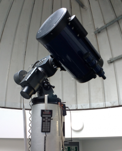
The large 38" JGT dome and the double domes of the Napier building next to it. (upper right in aerial photo below). The domes of the Napier house two Schmidt-Cassegrain telescopes with one being a 10″ and the other 16″ aperture. Photo shows the 10 inch in its dome.
A recent third small Pulsar dome has been added onto the flat roof of the Napier along with the 2 original main domes.
The dome that once held the double telescope (left in aerial photo below) is now an exhibition/art space. The double aperture 40-cm Twin telescope was dismantled in the late 1990s.
The photo below shows a giant Neon spectrum laid out with fabric strips.
The main building dome (the Scott-Lang building) contained a 50-cm reflecting telescope with a spectrograph (currently not in use).
On open nights several small optical telescopes are normally placed out on the flat roof of the Napier building for visitors to observe with. There are two 8 inch Meades and several smaller units including a Meade ETX80 refractor.
-
2
-
-
The James Gregory Telescope , St Andrews
Previously (before Covid) this was open to visitors on 2 open days a year as well as once a month during winter evenings.
Hopefully these opportunities will return in time. It is worth the visit to see this wonderful telescope.
The mirror is 38 inch , the Schmitt corrector 37 inch and it operates stopped down as a 35inch.
I recently discovered some fascinating historical film had been posted showing the construction of the mount/dome and the fabrication of the mirror.
Dome construction James Gregory Telescope - YouTube
Mirror assembly for James Gregory Telescope - YouTube
more information about the James Gregory Telescope (JGT) and its history can be found here
JGT – Observatory (st-andrews.ac.uk)
for those into the finer details there is a great "manual" for the scope JGT_manual.pdf (st-andrews.ac.uk)
The photos of the telescope below were taken on the last open night in Dec 2019
-
6
-


ideal camera for scope
in Discussions - Cameras
Posted
for CCD matching this site is handy
https://astronomy.tools/calculators/ccd_suitability
example shown for your ED120 and the 1600mm
remember to set any reducer or barlow you are using
(ED120 and 1600mm are a good match)