


vlaiv
-
Posts
13,106 -
Joined
-
Last visited
-
Days Won
12
Content Type
Profiles
Forums
Gallery
Events
Blogs
Posts posted by vlaiv
-
-
17 minutes ago, pete_l said:
Would they be poor? Most cameras have pixels in the 2.2-8µ range. When you look on astrobin you can see images at all ranges of pixel scale and it seems to me that pretty much any pixel scale can produce great images. A large amount of the success is in the skill of image processing.
Here's a link to NGC206 at .65 arcsec/px and here's an M31 at 4.8 arcsec/px (neither are my work). They are both very fine images.
I'm not saying that one can't make a good image with long focal length scope if they know what they are doing. I'm just saying that if people are looking for advice on which camera will serve them best - saying that good rule is fl = pixel size x 200 - when that particular rule will lead to oversampling in 99% of amateur setups, or mentioning that it is ok to use even double focal length without explaining impact of such decision, or how it can be mitigated, will do disservice more often than not.
It is also the fact that explaining all the intricacies of choosing particular sampling rate and processing workflow (like binning, etc ...) can similarly confuse people and do them disservice and should be done carefully as not to confuse or deter from understanding.
-
1 hour ago, pete_l said:
I agree with wimvb. It is easy to fall into the trap of decision paralysis based on the specifications of CCD/CMOS cameras. They tend to exaggerate the importance of small differences in the numbers. The underlying principles of all cameras is the same - with some advantages of CMOS (such as lower noise, the ability to "bin" in software and not lose much).
As for pixel size in general the "best" focal length for a given camera is the number of microns for a pixel multiplied by 200 (so a 5µ pixel is "best" with a 1000mm focal length). But the range over which it provides perfectly good and usually indistinguishable results is very, very, broad. I'd say from below 500mm focal length to over 2000mm - so the vast majority of imaging scopes.
")
I also would say that the technical difference between cameras becomes insignificant when compared to the results from manually processing the image and the skill and experience of the person doing that work. Unless you get a camera with a fault, almost any one will give you great results - once they are properly stacked and processed.
I think you are very much overestimating "best" focal length for a given pixel size. What is the criteria that you are using for this?
Sure you can use 5um pixel camera with 1000mm focal length for effective sampling resolution of 1"/px - but most of amateur setups are simply not capable of delivering that sort of resolution. One needs 1.6" FWHM stars in their subs to do that. Hence in most circumstances that will be oversampling.
Saying that you can equally use 2000mm of focal length with 5um pixel camera without mentioning how can you make it work is probably going to cause issues for most people that don't have deeper understanding of this topic.
I can imagine someone choosing C8 over 8" F/5 newtonian based on that reasoning and wondering why their images are so poor without realizing that at 0.5"/px they are spreading photons too much over pixels and that they need x4 more imaging time to match SNR of 8" F/5 newtonian with same camera.
-
There is a lot more to consider when choosing suitable camera.
I will give you two examples where simple formula like pixel_surface*QE can go so wrong.
For ASI1600 you obtained figure of 8.5 - that presumably being 3.8 * 3.8 * 0.5= 7.22 (in my calculator, but maybe you used different QE figure there - I've found it to be around 50% in quotations on the net). Actual figure does not matter for what I'm about to say - why don't you repeat your calculation but this time take binned x2 pixel size? Instead of going for 3.8 * 3.8 * 0.5, go for 7.6 * 7.6 * 0.5 = 28.88!
Now we are talking, right? It's clearly the best of all on your list above.
But hold on, binning must be cheating right? No, it's not - it's legitimately used and indeed it has the same effect as using larger pixel size (for hardware binning, for software binning like with ASI1600 it acts as larger pixel size and larger read noise - by factor of 2 so it is 3.4e instead of 1.7e at unity gain - but like you said yourself - read noise is not as important because it can be sorted out with longer exposures up to a point).
Here you go - simple example that your metric of pixel_surface * QE does no hold much sense.
Let's go with another example.
Atik 414Ex - it has something like 9mm x 6.7mm or 11.22mm diagonal and "figure of merit" equal to 22
vs again
ASI1600 which has diagonal of 22.2mm (let's simplify to double that of atik - it's not quite but almost).
Let's now take some common type of telescope - like F/5 newtonian and compare how will two sensor fare if we decide to shoot same size FOV with each mounted on suitable newtonian. It is clear that scope paired with ASI1600 needs to have twice focal length of that paired with Atik to provide same FOV. Since both scopes are F/5 - one paired with ASI1600 will have twice aperture as well - or x4 light gathering surface.
Which sensor do you think is going to provide better image on same FOV in same time? I would guess - one collecting x4 the light.
-
4 hours ago, ollypenrice said:
I'm a notorious doubter of the Crayford design in principle. Monty Python's Flying Focus...
 nly joking!
Olly
Yet you swear by Mesu - both being friction based products

-
 1
1
-
-
13 minutes ago, Redscouse said:
Is there a way to definitely recognise if i'm too short/long regarding backspacing.
IE: do the stars elongate horizontal if too close and vertical if too far? (or similar)
Might sound like a silly question but when testing I've no idea which way to go, do I add or reduce.
I think I've managed to achieve the correct distance now but it was a chore to get there swapping spacers/adaptors etc.Skywatcher ED80 & matching flattener/reducer. (0.85)
ZWO ASI 178MM & EFW.Yes there is a way, and indeed astigmatism will be sign of improper spacing - but not in your case. In your case it's best to just measure distance with ruler or similar.
ASI178 is very small sensor and above astigmatism effects start to show on sensors twice or three times it's size - that means that if you miss your target distance by +/- few mm - you won't be able to tell in central part of the image (which is what this sensor is covering). And since stars on your image already look round all over - you have correct spacing for this setup - when and if you get larger sensor - you'll adjust distance again.
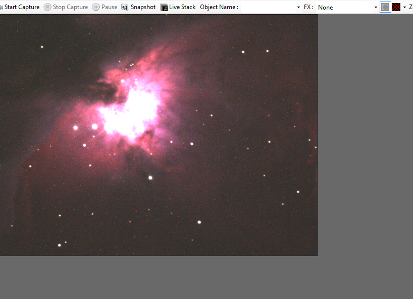
15 minutes ago, Redscouse said:Secondly, I've attached a single 90s sub using L filter (converted to png for this demo).
It looks to me like the whites are about to be overexposed however not much detail elsewhere.
Is this normal or do you have any suggestions regarding gain/exposure etc. that would help capture more signal without overexposing.
I've trialled from 60s up to 600s and it seems 180s gives me much better detail, however the whites are bloated.
I've never moved the gain or any other settings in the camera before so not sure if that would help?Detail is there, don't worry about it, it will be brought up with stacking and then histogram stretching - that is sort of normal workflow for astro image processing.
This is because dynamic range is extremely large in astrophotograpy. You can have stars that are 6-7 magnitude and galaxy that has surface magnitude of 22mag - that is almost 15mags of difference, or about x1000000 difference in intensity (x100 for every 5 magnitudes). Just because you can't see faint stuff on 8bit monitor (255 levels) - does not mean it's not there and will not show after stretching.
That sub that you did looks nice, and it looks like it is supposed to look. Maybe core of galaxy is a bit burned, but that can be fixed with couple of short exposure subs and a bit of copy/paste.
-
 1
1
-
-
Well, if you can call it that way, but yes, I believe it will be interesting EEVA setup.
First introduction to setup. I don't say this often, but this is one sexy looking setup:

Scope is SW Mak102mm mounted on AzGTI head and pillar that sits on Berlebach adapter (3/8" to SW mount tripods) and HEQ5 heavy duty tripod. Camera is ASI178mcc (cooled color version) mounted at prime focus.
Due to poor weather, this is only daytime testing so no conclusive results (well, some are - ones that will not work
). First baseline shot - sensor mounted at prime focus:
Target is roof of a house that is about 315m away (according to google maps / satellite view, and measure tool). Roof is indeed green (dark green - image is not properly color balanced).
This image shows full FOV, debayered using super pixel mode for effective resolution of 1548x1040 and scaled down x3 (to 33% size).
At full zoom (1:1 pixel) it looks like this:
It is rather cold outside and I was shooting from balcony and yes, there were thermals both from my own house and houses in between, but I think this image is pretty much indicative of sharpness so we can take it to be baseline.
First test was simple x0.5 GSO focal reducer in 1.25" variety. With this sensor, my aim was to get something like F/4.5. That would be reduction factor of about x0.346, so more than "prescribed" x0.5. I eyeballed distance to sensor so no precise reduction factor (one of things that I wanted to test out was reduction factor at certain spacers combination) and here is full FOV:
Pardon the orientation - I was to excited that it worked at all on that distance and that I had no issues with focus so I completely forgot to properly orient the sensor.
It is hard to judge sharpness here because depth of field is evident because speed of setup is indeed increased. Here is section of the roof at 1:1:
Now this is not smack in the center of FOV and roof is tilted and for that reason I believe that it is depth of field rather than off axis aberrations.
Length of tiles in both images are: 165px in prime focus:
and 65px with reducer:
Ratio of the two is ~x2.54 or as reduction x0.394 - very close to target reduction. With this distance setup is at F/5.12 and additional spacer of 5mm should push it down to F/4.5. Nice.
Next thing that I wanted to test out was eyepiece projection and I decided to try out "reducer mode" eyepiece projection method (as opposed to "proper mode"). Unfortunately, achieved reduction is way too large. Eyepiece used was 32mm and sensor was placed at about 27-29mm - that creates somewhere between F/2 and F/1.2 system (probably around F/1.6). This creates all sorts of havoc on optical performance of system (illuminated field is only about half to third of sensor size, and sharpness is well, very non sharp
).
Here is full FOV at this setup:
I did not debayer this image - just made it appropriate resolution (bin x2 of raw data). That is true mess. Let me see if I can pull out reduction factor and 1:1 image.
Actually it's not that bad:
Contrast is suffering, but that is because this is very aggressive reduction and this scope is not properly baffled! It really needs to have rather long dew shield to remove issues with baffling. You can see that there is bright outer part of the illuminated circle - that is due to unfocused light going thru front corrector plate and ending up on focal plane (very far off axis for normal use) without hitting mirrors.
Anyway, tile length here is about 27px, so reduction factor is about x0.164 and that applied to F/13 system gives F/2.12 (so distance is about 27mm). To be usable configuration, I would need to bring it forward 6mm (to about 21mm) and that is simply impossible with eyepiece projection adapter that I have and this camera model.
In the end, there are couple more things to try out for results - proper mode eyepiece projection (with distance to eyepiece of about 43mm - so T2 extension of 16mm will be needed - I can get 15mm, that is 10+5mm) and afocal method with CS lens for this camera (about 12mm lens will be just right).
And night time trial as well - that one is probably the most important
If everything checks out - we will have very interesting beginner setup that can do it all - visual for planets and DSO and planetary imaging and DSO imaging (in form of EEVA rather than proper imaging, but I also plan to test this scope with a bit more serious sensor - ASI1600 mono + filters - to see what it can deliver if data is processed accordingly).
-
 7
7
-
-
1 minute ago, Kev M said:
I read that as the other way around.
F ratio would only be meaningful at "the same aperture" surely ?
F ratio is meaningful at same pixel size and without binning.
If you fix pixel size then aperture / focal length ratio determines "aperture at resolution" because at fixed pixel size aperture = aperture and focal length = resolution, so ratio of the two determines aperture at resolution.
-
How was this image processed?
I suspect that drizzle integration was done for some reason as image size (height x width in pixels) is twice the size of sensor pixel count?
Drizzle integration is going to lower SNR and as is, 3.1um pixel at 1200mm FL is already oversampling by factor of x2 at least. This means that you could have at least x4 SNR if properly processing the data.
-
12 minutes ago, ollypenrice said:
So, dual refractors or fast reflector???
Oh, I know answer to that riddle - quad fast reflectors
6 hours ago, Louis D said:Visually, I find stars are tighter in my refractors versus my Newts. I've always attributed it to the CO pushing light out of the Airy disk. It's one of the main reasons I like them despite the smaller aperture.
It is common misconception that central obstruction is the main reason for size of the stars in images. In images stars are usually number of times larger than size of airy disk.
This is even true for visual - let's compare 80mm unobstructed scope with 130mm obstructed scope (25% CO) to see which one is going to give tighter stars (if CO and aperture are only difference).
First a bit of math - from this wiki article we can see that first minimum in Airy pattern (where disk ends) corresponds to first zero of Bessel function of first kind of order one. Other zeroes represent dark divisions between rings.
Now let's compare where "disk ends" for first aperture to disk+first ring for larger aperture (we can take lambda to be the same):
First minima of small scope: 3.8317 / PI * 80mm = 0.015246 (some units or other)
Second minima of larger scope: 7.0156 / PI * 130mm = 0.017178 (again same units as above)
This tells us that even if central obstruction is pushing light into rings - airy disk + first ring of larger obstructed scope is almost the same size of only airy disk of smaller unobstructed scope (in this case difference is ~12% larger).
To get the idea of how it looks side by side, we can do images of both and compare them as they would look visually if there was no atmospheric interference and we were observing them on same magnification:
-
2 minutes ago, Bobby1970 said:
Thanks for the info John.
I don't want to go just throwing money at something that's no improvement on my 450d.
I just assumed that something like the 183 would be "more sensitive" than the 450d. But happy to be corrected.
Thanks again.
Not something that is easily asserted - as it will depend on scope used and what will be it's primary use case (DSO imaging or EEVA)
In any case, I also vote for cooled version of any camera over all other (even for EEVA).
-
Indeed - we need linear data from both to be able to compare them in meaningful way.
In fact, best way that I've found for comparing such data is "split view" sort of thing - both images are normalized while in linear stage and half of each is used to compose final linear image (left half one image right half second image). Then you can see how certain level of stretch and processing impacts both images and compare based on that.
-
1
-
-
4 minutes ago, tooth_dr said:
I’m looking at all my old ED80 images and the stars are smaller and nicer.
In comparison to this ED80 image or 180ED one?
-
10 hours ago, tooth_dr said:
There was high cloud / poor transparency when I collected the 180ed data on Xmas eve. And I’m not totally sure I’m exactly in focus. Still doing it by eye, and my focus step is 17um but my CFZ is 10um.
Less than perfect focus can surely contribute to star softness.
-
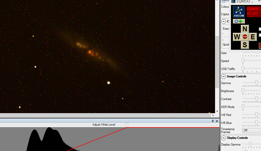
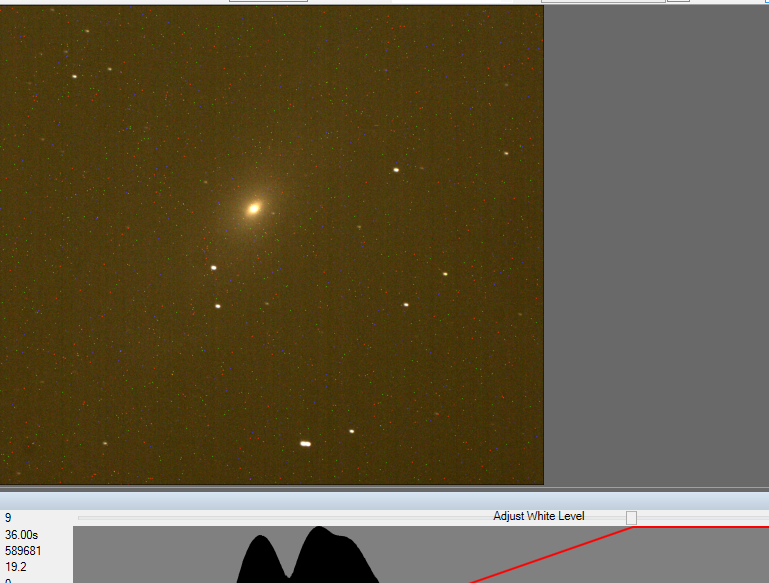
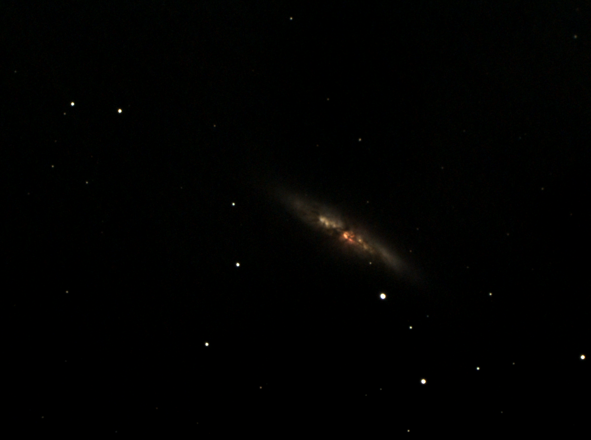
Very interesting comparison.
Same camera and same focal length (almost - but let's say it is) - ED80 image is less noisy as is expected - aperture alone is x5 (without accounting for double mirror coating and central obstruction of 180ED) but exposure time is x10:
vs I believe that ED80 image is sharper - better resolution, which is very strange because of aperture difference. It looks like seeing dominated imaging and was in favor of ED80.
vs stars look tighter in left image - ED80.
-
4
-
-
Usually I would recommend 071 then 294 and 533 last, but lately there are a few people having issues with these OSC cameras (071, 294). I'm not entirely sure why is that - whether it is their particular setup or something else. For this reason I'm a bit reluctant to give recommendation without any reservations. It could be that these people have issues with the way they are using their cameras (light leak, driver version, improper flats, ... there could be rather large number of reasons), and there is probably much more people out there using these cameras that are not complaining (and have them working fine).
In any case - EdgeHD has very long FL and I think that you will be best served by 071 model. With x0.7 reducer that will give you be sampling at ~1.4 (if you use super pixel mode) and will have decent FOV for DSOs
Here is comparison of FOVs on some targets:
-
7 hours ago, Gan said:
Let us suppose budget could be stretched a bit, which following parametrs would carry more weight? ( for DSO photography) : 1. Resolution ( arc sec/pixel) 2. FOV 3. resolution ( pixels) 4. Read noise 5. Pixel size 6. QE 7. Full well capacity 8. FPS
(The contenders then would perhaps include ASI 071, which is £500 more expensive)
I'm going to expand a bit on this from my previous answer which was rather short (as I was short on time, but I have a bit time now to be more elaborate).
First items 1, 2, 3 and 5. - here is what I recommend:
For scopes up to 4" in diameter, you should keep your sampling rate below 2"/px (below meaning higher number of arc seconds per pixel or lower sampling resolution). For scopes between 4" and 6" you can go with 2"-1.5"/px, for scopes 6"-8" you can go 1.5"-1"/px and for scopes 8" and above you can go with 1"/px.
That is based on size. You need to account for seeing conditions and also for your mount and guiding accuracy. In any sort of good seeing you will be limited to 1.5"/px and you need really good seeing to go below that (excellent seeing to go at 1"/px). You also need guide RMS to be at least half of target resolution if not less than that.
This all means that your realistic sampling rate is 1.2" - 1.5" per pixel for larger scope, 1.5"-2.0" for medium size aperture (about 6") and 2.0"/px and above for 4" and lower. Going for 1"/px is extremely difficult and you need large aperture scope, excellent mount (guide RMS of about 0.3") and excellent seeing conditions.
What does that mean for FOV and pixel size and resolution? Well FOV is determined by sensor size and focal length of scope. Larger sensor will be "faster" sensor - but only if you pair it with suitable telescope.
If you have your FOV set - for example you want to image galaxies and you have idea of your FOV to be approximately 40' x 30'. You can make that work with almost any sensor size, but you will need suitable focal length. You can do it with sensor that is ~15mm in diagonal, let's go with ASI183 and you will need something like 1000mm of focal length for that.
If you choose F/5 scope for this - you will work with 8" scope. Take ASI294 now and do the same FOV calculation. You will need something like 1500mm of focal length - and if you work with F/5 scope - that will be 12" scope.
So in first instance you have 8" of aperture gathering light for your FOV, while in second case you have 12" aperture gathering light for your FOV. It is clear that second case is faster - larger chip wins because you can record same FOV with larger scope (of the same type - but this costs more).
Now that you have your FOV set, and let's go with above case - 45' width (0.75 degree) at 1500mm - now you need to see what sort of sampling rate will you get. You have flexibility here, because you can bin.
First thing to realize is that you are sampling at twice the rate when using OSC camera (that also means that there is no benefit in using any other debayer technique than one that provides proper resolution - like super pixel mode).
Let's say that you want to sample at 1.2"/px, that means for OSC sensor that single pixel should be 0.6"/px. We have 45' to cover, and that is 45x60 = 2700 arc seconds. We need a sensor that has 4500 pixels in horizontal direction (2700/0.6). ASI294 has 4144, so we are going to sample a bit "coarser" than 1.2"/px (which is still ok). We will actually sample at 1.27".
So you see, all above variables are connected, and you need to take into account:
- what sort of scope are you going to use camera with (maybe multiple scopes?)
- what targets are you going to go after with that camera (and particular scope)
- what sort of performance can you expect from your mount and skies
- take into account any binning and such
Then you can do comparison of cameras based on points 1,2,3 and 5 combined.
4. Read noise
This one is essential thing when doing planetary imaging, but for long exposure AP it is not crucial. It will only impact duration of your subs. Only difference between stacking multiple subs and taking one long exposure is in read noise (well, this is not quite true, there are other benefits to stacking like hot pixel removal, airplane/satellite trails removal, rejection of frames that have quality issues - like wind shake or passing cloud and such), but in mathematical sense - for ideal exposures, only difference is in read noise. If read noise were 0, then stack of many subs would be exactly equal to single exposure of same total length.
Since read noise is not 0, more shorter exposures will always be lower in SNR than fewer longer exposures for same total imaging time. There is but - how different will depend on how high read noise is - compared to other noise sources (and not it's absolute value).
If there is strong light pollution - it will contribute quite a bit of noise that is larger than read noise - you can go with short exposures.
Your camera is not cooled and there is thermal noise? - Again you can go short exposures and you won't be able to tell the difference.
You are in very dark skies or you do narrow band imaging - you need to go with longer exposures, because difference to shorter exposures will show.
Overall - for regular long exposure AP, you don't need to worry about read noise levels. If they are really low - like less than 2e, you can use 1-2 minute exposures in LP and 3-4 minute exposures in darker skies. If it is a bit higher like 3-4e - you simply go with longer exposures - like 3-4 minute in LP and 5-6 in dark skies (or even up to 10).
In the end you don't want to go overboard with exposure lengths because of things mentioned - algorithms work better when there is more data (more subs) and if you end up throwing away data - it's better to throw away one sub of 2 minutes than one of 20 minutes in length.
FPS - important only for planetary imaging
Full well - completely unimportant for imaging. You will likely saturate your sensor on bright stars regardless of how deep your full well is and there is really simple technique to deal with that - just take couple (and I mean really just a couple - like less than 10 is perfectly fine) - short exposures - 15s or so (even less if you have bright star that is saturating that) - and stack them separately and just use that stack to fill in original stack in saturated places.
For stars you really need only color (but we are talking about OSC cameras, so we are capturing color only) and for bright parts of target you will also need luminance (in case of LRGB and OSC).
QE - yes, very important. Really is - higher the better, no doubt about that.
-
1
-
-
3 hours ago, Gan said:
Let us suppose budget could be stretched a bit, which following parametrs would carry more weight? ( for DSO photography) : 1. Resolution ( arc sec/pixel) 2. FOV 3. resolution ( pixels) 4. Read noise 5. Pixel size 6. QE 7. Full well capacity 8. FPS
(The contenders then would perhaps include ASI 071, which is £500 more expensive)
That sort of question does not have a definite answer.
1, 2, 3 and 5 are connected and depend on several factors - namely what scope you want to use it on and what is your mount performance like
4. depends a bit on mount performance - how long can your subs be, but also on level of light pollution - is there a need for longer subs
6. Very important and does not depend on anything else - aim for the best value once you balance all other things.
7, 8. Totally irrelevant
-
What scope are you using?
If it has secondary spider and tube rings you need to align two things rather than just camera between sessions.
Only thing that camera rotation with regards to previous session brings is reduction of field of view:
Software is capable of rotating subs to match each other, but resulting stack will have all subs present only in narrow central region (red rectangle above). Large rotation reduces surface considerably while small angles almost have no impact and only outer edges need to be cropped away.
You rotate your FOV by simply rotating camera in the focuser - you have 2" nosepiece? then just loosen it and just rotate camera and tighten it back again. Angle that you rotate it will correspond to angle that FOV rotates but direction is not easy to guess (depends on type of telescope - every mirror flips direction, etc ...).
Issue with secondary spider is that you need to orient OTA relative to RA/DEC the same way otherwise your diffraction spikes will not align and you will get multiple X patterns overlapped on stars - which looks bad. Something like this can happen:
Keeping OTA fixed in tube rings and just releasing dovetail from mount clamp and reattaching it next time will keep OTA orientation (don't take tube rings of the ota, nor loosen them and rotate ota inside rings between sessions).
-
Since you mentioned 8" SCT for imaging - I would say go for ASI294, but given that I've seen few people having some sort of issues with them (and I don't know what it is due to) - I can't give that recommendation.
Btw, 533 is not related to 183 in any way except maybe sensor size.
Both 183 and 533 are smaller sensors and are going to have rather tiny FOV on 2000mm of focal length. 294 is larger and FOV will be better.
183 has tiny pixels and 533 has larger but still rather small pixels (compared to 294 and DSLR sensors). 533 is square sensor, and initial impressions are that it is rather good.
Not sure what to recommend.
-
42 minutes ago, RobertI said:
Thanks @vlaiv very useful to know this. I use a Lodestar mono, I was thinking that the F6 might not have enough inward focus for imaging with a reducer (as it’s not optimised for AP) but looks like it would be ok? I currently use an RC6 with good results, but it seems overly complex for EAA and I can’t help thinking a newt would be easier and I can use it for visual too.
Reducer that I used is this one:
It is 1.25" screw on reducer that can be easily sunken into focuser tube. I actually flipped lens on mine - it gave better stars in that configuration (I unscrewed retaining ring - took the lens out, reversed direction and returned it in the cell).
This reducer has focal length of about 101mm-103mm (source AgenaAstro website), which means that it should be placed at about 51mm away from sensor for x0.5 reduction (this is from lens itself - not from thread on cell).
When used like that, required inward focus travel is
50mm.
TS website says that focus position is approximately 50mm above 2" receptacle
I did not have issues with my 8" F/6 scope and focusing, but that might have been because camera at the time was 1.25" body type and could be sunken into 1.25" nosepiece adapter together with reducer.
-
1 minute ago, RobertI said:
well perhaps F6 would be better for visual and more apo like, but then not really useable for EAA anymore.
Hm, how do you do your EAA? What sensor size do you use?
Don't see why you could not do EAA/EEVA with F/6 scope, small sensor and x0.5 reducer. I've done it with 8" F/6 scope. FOV is small, but it worked:
In fact it worked so well at the time, that I decided to do some imaging in that configuration and ended up with these:
There are all taken with 8" F/6 scope and x0.5 reducer and QHY5IILc camera. Notice absence of coma because of small sensor and F/6 scope.
Lodestar which is mono and has 50% larger width and height and much larger pixels (at least x2 in both width and height) is going to be much better.
-
1
-
-
2 minutes ago, Marmo720 said:
Thank you for the analysis. Yes I noticed the bunnies dancing too.
My camera to telescope is pretty firm but I only have 1 second wait between flat exposure so will change to be longer and see if that fixes the issue. My flat panel is inside the original box with circle cut to allow the dew covers inside and block outside light. It rests on the dew cap when I take the flats so I don't touch any part of the imaging chain.
The two flat-flat calibration, is the first one the flat panels (the good one) and the second set is the iPad? If so, I will stop using the iPad and stick with the lightbox.
Carole showed me how to do the flats manually so I can change the exposure time etc so will try 1sec instead of the current default APT plan.
Thanks again.
Yes, first one is with light box and I would recommend that you use that one.
There is however concern about third set of flats - color balance issue (look how different histogram shape is for some reason). When doing AP it is best if you leave everything on "manual", don't use any auto features, don't color balance your data on camera and such - just shoot raw data. All that stuff can be done in processing and it should be done in processing after calibration is finished.
I have no idea why should things jump around so much after each sub, but they do. That is going to cause you problems later on in imaging as same things will happen with lights as well.
-
I'm afraid these flats are a mess on multiple levels

First let's start by the fact that again - all flats are underexposed by quite a bit.
Here are full range histograms of each of these flats (or rather master flats made from 5 flats of each group):
All are underexposed as you can see - they are not even at 10% or so and they should be at 80-85%. This means that you need to increase flat exposure by factor of about 8 times. I see that you had 1/8 second exposure for one set of flats - why don't you try 1s exposure next to see if you will properly expose flat. Use flat panel when doing flats.
Flat panel works better than iPad - here is what average value of flat exposure across flats looks like (flats 1-5):
Very small variation in mean value (good).
For comparison - same measurement for iPad (frames 21-25):
Much more variation between numbers - as if panel is flickering and producing different intensity light.
Histogram for first master flat (flats 1-5) looks as it should (except for being under exposed):
So does second master flat (flats 6-10), but third one (flats 11-15) looks different:
As if color balance changed or light source changed.
Even stranger looks iPad histogram (flats 16-20) as it shows only two peaks:
so does second iPad histogram (flats 21-25).
Out of all of these flats, flat-flat calibration is worth trying only on first two master flats and last two master flats (two of flat panel, and two of iPad):
Flat-Flat calibration (with missing bias, but let's do it anyway) of first two master flats looks like this:
That actually looks rather decent. Yes there are dust bunnies all over the place (I'll explain cause of that later) - but it is actually rather flat image (look at histogram, it is bell shaped and looking ok). Here is what it looks like filtered for noise:
There is very small gradient visible - if I stretch it it will look horrible like:
But these are variations less than 1% in intensity (from -0.5% to 0.17%). Due to fact that we did not remove bias - this is rather good.
Now second flat-flat calibration:
This one has obvious gradient and I would not call it success. Here it is smoothed out:
This gradient is now 3% wide compared to above less than 1%, so it is noticeable.
In the end, I would say that something is very wrong with the way you are taking your flats - look at this animation - it shows differences between flats of same settings (animation shows stretched flats 1-5):
Dust shadows are dancing around! Even large doughnut in the corner seems to be shifting between subsequent subs. What could be shaking your setup so hard that dust particles are dancing around? This happens on all the frames that you uploaded - some have less of shake and some more.
If you are manually triggering your camera - maybe set 2s delay (or even 10s delay) to let your scope and mount settle. Maybe look into mirror lock so it does not move out of the way each time and cause vibration. How firm is your setup? Is scope/camera connection tight and firm? How is flat panel attached to the scope? Do you hold it against the scope yourself? It would be best if you had means to mount everything without holding anything yourself and not touching either scope or camera (remote shutter release).
-
I think @iPeace used one for lunar and it was very good.
There is a thread about it, but I can't find it right now. Here are couple of threads of that scope being mentioned:
-
2
-
1
-


 vs
vs 
 vs
vs 


Bortle scales and Millicandela measurements
in Observing - Discussion
Posted
Maybe best type of unit to be used is mag/arcsec^2, or simply magnitude (surface brightness - not to be confused with stellar magnitude although it is the same thing).
Magnitudes are better suited to our visual perception than physical quantities because our eye/brain works on close to logarithmic scale.
Surface brightness of targets is also given in these units (or mag/arcmin^2 and here it is simple conversion as add 8.89 to get mag/arcsec^2 - but these tend to be average brightness) and you can estimate visibility from that.
According to SQM calculator page (found here), to convert from cd/m2 to mag/arcmin2 use:
or rather opposite one in above case.
We have 0.24 mcd/m2 and 0.21 mcd/m2, let's convert that to mag/arcsec2
-2.5*log(0.00024 / 108000) = 21.633
-2.5*log(0.00021 / 108000) = 21.778
How big a difference is 0.14 magnitudes? Not much - change in transparency from excellent to very good will make about 0.1 mag attenuation of targets. Single air mass has about mag 0.16 attenuation.