


vlaiv
-
Posts
13,106 -
Joined
-
Last visited
-
Days Won
12
Content Type
Profiles
Forums
Gallery
Events
Blogs
Posts posted by vlaiv
-
-
3 hours ago, dannybgoode said:
Could it be that might guide scope had not fully cooled?
Like @wimvb said, unlikely - small finder will cool down fast, and I believe that tube currents will cause effects similar to astigmatism - which will cause soft image for planetary, rather than causing guide star to jump around.
-
4 hours ago, Tommohawk said:
Either way, LUM is nothing more than the sum of R G and B data,
Lum is much more than sum of R, G and B.
For example - if you were to create synthetic lum, and you took 1h of R, 1h of B and 1h of G and you stack those together - you will get poorer result than doing 1h of lum. Difference will be in read noise (if there were no read noise 1h of each R, G and B summed would be the same as single hour of Lum).
This means that 3h total of imaging will give you poorer result than single hour of lum. Lum is good, otherwise people would not use it.
4 hours ago, Tommohawk said:and all darks have min value 16,
That is bad - it means that your offset is too low. You want none of your subs to have any value equal to 16. There is nothing you can do now to fix your data - but you can increase offset for future use. Make it larger than 50 or so (I use 64).
-
Actually there is much more to this data if processed properly. Due to original stack having only limited amount of data, but being rather large pixel count (6000 x 4000) and due to fact that stars are not quite good - we can safely bin that to regular size.
I've chosen bin x4 for picture size of 1500 x 1000 - which I feel is good representation of the image. Here is green channel extracted and treated as luminance layer (green in cameras is modeled as human vision sensitivity to brightness - so in principle it is ok to use it as luminance - add to that fact that sensor is twice as sensitive in green than in red or blue due to pixels in bayer matrix ...).

Here we can see full extent of M42 but also the Running Man above. Stars are also tighter in green because lens used is not well corrected for color and there is blue fringing otherwise.
-
 1
1
-
-
Ok, so here are steps to get basic stretch done in Gimp. I'm using Gimp 2.10.4-std windows install.
- Open up your tiff image in Gimp
- First step would be to use levels to do initial stretch so go to Color / Levels menu option and do following:
Take top slider and pull it left until brightest parts of nebula become bright enough - don't turn them white - that will clip detail. In your image - 4 stars of trapezium are not resolved and are burned out already, but you can watch nebulosity around them - as soon as it starts being too bright - stop with adjusting levels. It happens somewhere around 50 out of 100 (or slider half way to the left).
- next step is to move middle control in levels. Again go to same menu option - Color / Levels and this time adjust middle slider like this:
This is part you need to do by feel - as there is no particular guideline on how much to pull it - effects of it will be seen in next step, so if things are not good in next step - undo and repeat this step but less aggressively (less to the left).
- Third stretch with Color / Levels resets black point to it's regular value - again do the same Color / Levels but this time we move black point - or left most slider like this:
Here, rules are simple - you need to pull black level marker up to the foot of histogram. If your background looks too grainy and bad - you overdid previous step, undo it and repeat with less aggression. It is ok if there is a bit of grain in the background - we can fix that with denoising later.
- Next step would be slight curves stretch to bring out brightness of features. We do it via Color/Curves command, and we do following:
We need two points - one "anchor" point that we will not move - put it somewhere on the base of histogram - just make sure you don't move it - line should still be diagonal. Next you take a point somewhere on the middle and drag it up until you get nice brightness of the features - don't over do it as again you run a risk of burning out core (bright regions).
- Next step would be slight color correction - as image now has red cast due to LP. Simple way to do it is temperature correction:
Move intended temperature slightly lower and original temperature slightly higher - observe what happens to the image and stop where you feel it is good.
- next, let's do a little denoising. Select that layer and duplicate it:
select top layer and run menu command: Filters/ G'mic-Qt and select repair / Smooth (wavelets). Increase Threshold until you get rather smooth image:
after you need to add layer mask on this smoothed image - right click on that layer and add layer mask:
Set mask to inverted and gray scale copy of layer:
After that you can use that layer opacity to control how much noise reduction will be applied to final image (it will be more applied in dark areas due to layer mask - but with lowering of opacity you can have further control).
And voila - save your image and present it:
-
5
-
-
11 minutes ago, Tommohawk said:
Also not sure how to check the ADU values in the darks - can I see this with FITS liberator? FIT lib image headers shows Gain 139, BLK LEVEL 25 - this is the offset maybe?
Don't think it makes any difference that your camera is not pro - neither is mine and I've never had those issues. It is quite possible that SharpCap is for some reason at fault here, but just to be sure - fits liberator will give you details that you want:
This is one of my 240s darks at -20C with offset 64, it has min value of 80 (needs to be larger than 16).
There is one more thing that you can check to see if everything is all right (I've come across that being issue so we can make sure all is fine in your case) - make max zoom on preview and move mouse cursor over the image and observe single pixel values that are being displayed in info section - pixel values need to be divisible with 16.
If you notice any number that is not divisible by 16 (and it is easiest to see that if any pixel value is odd rather than even - then it's not even divisible with 2), then we have a "problem" of some sort. This needs to be done on uncalibrated raw files straight from camera (darks for min value, and both darks and lights for values divisible with 16).
-
3 minutes ago, geeklee said:
Thanks again @vlaiv I think the penny has hopefully dropped.
So, taking two final stacked images (short Vs long exposures)... If they were initially stretched in the same way (e.g. same levels/curves), the longer exposure stack would look "brighter" and "show more detail" but only because the image started off with higher values in the pixels? Putting it another way, the stacked image from the shorter exposures needs additional stretching to get it's brightness and detail to the same level, but presumably it can take this further stretching due to the related SNR?
If I've got this all wrong, I think I can just lose all hope and just accept it 😁
That is right. You don't need separate levels of stretch - you can use same levels of non linear stretch with simple multiplication before that, or you can use different levels of stretch - in that case difference between stretches will be that multiplicative constant.
Difference between these two images is really multiplicative constant (provided that there is no read noise and we have infinite SNR - or if we just observe signal and not noise) - same multiplicative constant that differentiates stacking by summation and stacking by average - in average case you end up dividing with number of subs, but if you want to go in reverse and from average get to sum case - you need to multiply with number of stacked subs.
In case of subs of different duration - multiplicative constant is ratio of exposure lengths - that is all you need to bring those two stacks (provided that they were stacked with same method - for example average) - to same value.
-
Ok, yes, you have option to save your image stacked in certain format
Then you will be asked to choose a format - choose either 32bit fits or 32bit tiff (maybe this second as it is more compatible with image manipulation software - first format is for astronomical use)
Also don't apply any of adjustments, in fact - don't do any of adjustments at all.
Once you have your image (but it looks like you already found autosave.tiff - above, you can use that as well) - you can upload it to some file sharing service or google drive or whatever.
Maybe simplest one is we transfer. Just upload it there and you can share the link - it will last couple of days (after that your file will be removed from their servers and link will no longer be valid).
-
1
-
-
Don't try to process things in DSS.
Just stack image and save result as 32bit tiff or 32bit fits file. Use latest Gimp to do basic stretch of the image and a bit of color balancing. Maybe try minimal approach first.
When stacking image in DSS there is option for background calibration - use RGB background calibration (that should preserve nice gray background).
If you want, you can upload result of stacking (still linear - don't adjust histogram in DSS) and I can show you first basic steps in Gimp.
-
27 minutes ago, geeklee said:
the 60s exposure should have a pixel with an ADU 6x larger (and thus a brighter pixel).
Ah ok, yes, brightness of the pixel is something that you assign rather than it is fixed in stone.
We do this in stretching phase. Let take above example and make e/ADU = 1 for simplicity and continue using e (less to type). You can decide that 6e is very bright and assign it brightness value of 90% or you can make it very dim and assign it brightness value of 1% - that is up to how you present your image.
What is important in the image is ratios of things rather than absolute value. There are two important ratios in our images. First is of course SNR and second is ratio between signal or ratio between pixels if we exclude noise. In principle - these two are the same thing - except in one case we have ratio of two good things and in other we have ratio of a good and a bad thing
 .
.
Now that we know we need to look at ratios - let's to again above example with signal values to see what we get (let's for the moment leave noise aside). Let's say that we have in first case 6e and 3e (effectively being 6e/min and 3e/min) and in second case we have 0.1e/s and 0.05e/s. These are same flux values, or same brightness values if we compare them in same amount of time (make both /s or /h or any other time unit).
But when we stretch our image and make 6e to be really bright - let's say 80% brightness and we want to keep "ratios" so that we know if something has half the value it will have half the brightness - we will assign 40% brightness to 3e value.
Our image thus becomes 80% and 40%. (Btw that is linear stretch - opting not to keep ratios creates non linear stretch and when we want to show really faint stuff - we assign larger brightness values than that faint stuff would otherwise have if we kept ratio the same).
Now let's stretch our 0.1e and 0.05e image. Again we want 0.1e part to be bright and we assign it 80%, then we ought to assign 40% to 0.05 because it is again half of intensity / brightness - we end up with 80% - 40%, or some image as above.
Absolute brightness values are not important for presenting content of the image - only ratios of intensities are important. If you take image and make it dimmer - it will still contain same image. In fact in bright room you watch TV and you dim it down. It now looks too dim and you may think it is now different image because you can't make out some things that are in shadows - but don't change anything on TV - just pull on curtains and kill all the ambient light and look at your TV now - it shows nice image with all the details again.
Another way to put it is - image does not change if you look at it from a distance. Let's say that you have painting and you look at it from 2 meters away. Now move 4 meters away - is it different? No? But absolute values of photons reaching your eyes just halved (or is that factor of x4 less? flux goes down like surface, so x4?)! Same image regardless
-
1
-
-
12 hours ago, geeklee said:
@vlaiv Typically stacking is an "average" method - a fundamental question that niggles on my general understanding is that long exposures must capture a lot more faint detail as you must be averaging a higher number of photons/electrons Vs a short exposure. If that question makes sense? Can you clarify where my thinking is likely going wrong?
There is not difference between stacking with average and stacking with summation. There is in sense that you will get different absolute values, but you will still get - same measured value (but in different units) and same SNR. Average is just sum divided with number of samples, so mathematically, difference between stacking with sum and stacking with average is just constant multiplication.
In measured value sense - it is best explained like this. Imagine you have 60 exposures of one second. Stacking with average will give you value that corresponds to "per second" measurement - if you have calibrated subs to read photons - it will be in photons per second. Stacking with sum will produce same measured value - but this time expressed in "per minute" - again if you calibrated for photons it will be photons per minute (or we might simply say ADU per second or ADU per minute if you did no calibration).
For SNR it is easy to see that ratio of two numbers does not change if you divide them both with some constant - so SNR does not change.
Having said all that - let's address level of captured detail in few long subs vs many short subs - or rather myth that short subs don't record faint stuff. It is easier to look at it via stacking by summation - as it shows that on average you capture same amount of photons for same total time although you capture much less photons per single short exposure. I gave that example above, but let's go with average to see what happens then (it will be same thing):
Let's imagine we have a source that gives off 6e/min/px with our setup (we will omit /px and just say signal is uniform and we observe single pixel). In one minute exposure we will certainly have 6e on average, so if we stack 10 minutes - we will again have on average value of 6e.
6e / minute means 1e every 10s or rate of 0.1e/s. Now imagine you have 600 subs - each long 1s. Each of them will have 0.1e. But hold on, you will say - electrons come in chunks and you can't have 0.1e - and I agree, you will have 0.1e per sub on average - or we could say that 9/10 subs will have 0e and 1/10 subs will have 1e (or some other distribution that will average out to 0.1).
Now we take those 600 subs and average them out - what do we get? Value of 0.1, but since we are averaging 1s exposures - it will be value of 0.1e/s.
People will often say - in first case you have 6e value and in second case you have 0.1e value - surely 6e is larger than 0.1e and therefore signal is larger! But what about units? Let's see when we have same units 6e/min = 1/(10s) = 0.1e/s - they are the same value.
If read noise is 0 and all other noise sources depend on time - and they do depend on time because they depend on quantity that grows with time - stack of many short exposures will be equal to stack of few long exposures (for same total imaging time).
In video that you have linked there is talk of max sub duration after which there is practically no difference in achieved SNR and this max sub duration depends on ratio of read noise to sky flux - when it is lower than certain value you can stop increasing exposure. If we take that read noise is 0 - for any sky flux this value will be zero and smaller than threshold value - you can use any sub duration and result will be the same.
This means that there is signal in any sub duration - although it might seem like there is none.
-
2
-
-
3 minutes ago, Tommohawk said:
It's a bit streaky probably due to fixed pattern effects which this camera is known for and apparently should fix with dithering
Dithering will certainly help there, but this should not happen regardless. I never saw it in my images with ASI1600, but have seen it with other sensors where I could not calibrate it properly.
I'm specifically referring to this one:
background striation effect.
Now FPN of ASI1600 is something that will in principle calibrate out if you use enough calibration subs and residual will act like regular noise unless there is some disturbance in distribution - like improper offset and clipping. You can check if that is the case by examining your dark subs. Do any of them have ADU value of 16 anywhere in pixels? (or value of 1 if you divide with 16 each sub to make it 12bit value) - run a stats on any dark and see what the min value is - it needs to be higher than 16 if offset is properly applied.
-
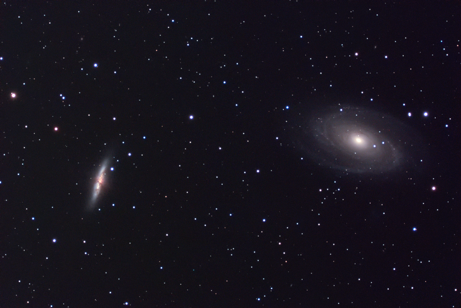
Apart from the fact that color balance is quite a bit off, and that you have issues with background and red star halos - very nice image indeed. So let's address some of those issues.
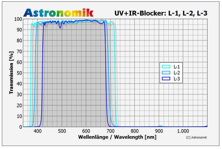
First off, in order to control star size you should really use lum - but not any lum filter. If your scope is not well corrected - and by the looks of it and your story - it seems to be not so well corrected - you need to use "special" lum filter - astronomik L3 (I think, let me check that) - indeed it is L3:
It will prevent bloating from both blue side and also from red side of things as it finishes rather early on both sides of spectrum. Bloating is due to unfocused light - and most of it will come from either sides of spectrum. Cut those "wings" and you have yourself smaller stars.
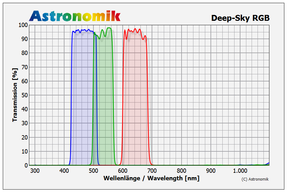
Since their RGB filters also follow this - L3 curve, maybe swap red as well?
Now for background. I'm seriously surprised that you have such background on ASI1600 cooled version. I've seen such background before and it almost always comes from CMOS sensors that are not cooled and as far as I gathered - it is related to offset and calibration.
What offset did you use, and how did you calibrate image?
-
1
-
-
Just now, GiorgioF said:
Uhm... You make me thinking.
I always got that cmos give no improvement but your explanation has some base to be considered.
As soon as weather will allow me, I will try to gather O3 (that is always weak) with bin2x.
Thank you!
When binning cmos images - don't do it while imaging - record as you normally record - at full resolution.
Then in processing stage, after you calibrate your subs and before you start stacking - bin them and stack them binned. Since you are using PI - binning is available as integer resample tool.
Here is documentation page explaining it:
https://pixinsight.com/doc/tools/IntegerResample/IntegerResample.html
Just set method to average when down sampling and down sample by factor of x2 or x3. You don't have to wait for additional data - you can do it on data that you already have.
-
10 minutes ago, GiorgioF said:
I agree about binning but with my cmos there is no advantage unlike ccd
That is not true. Any sort of binning produces improvement in SNR - regardless if it is software or hardware type of binning. It is same thing as stacking - you average values and average will be closer to true value than single values.
Difference between hardware and software binning is in amount of read noise you end up with. All other noise sources are treated the same. If we observe 2x2 binning - with hardware binning you will get slightly above x2 SNR improvement (how much over x2 depends on how big contribution read noise has), while with software binning you will get exactly x2 SNR improvement - per sub. When hardware binning 2x2 - signal is increased by x4 but read noise stays the same. With software binning signal is increased by x4 but read noise is increased by factor of x2. That is only difference (and the fact that you can do software binning in numerous ways - which can actually produce better SNR results than hardware binning).
-
3 minutes ago, rickwayne said:
If your exposure is too short, the electrons generated by the dimmest parts of your target are too few, and it's hard for stacking to discriminate their values.
This is common misconception - there is nothing wrong with using very short exposures to do DSO imaging. Even exposures that don't capture single photon from a target can be stacked to produce good results. If photon arrives every ten seconds, then yes, we will capture 6 photons per exposure in one minute exposure on average, but we can also "capture" same signal using 1 second exposures. I'll just phrase it correctly and you will see why it is so - on average 1 out of 10 subs will capture photon, and when we stack those 10 subs - if we use summing - we will have total of 1 photon from target (on average) - if we stack 60 such 1 second subs - we will get 6 photons, so again 6 photons per minute.
Every sub captures signal, but also captures the noise - and that is why we have difference between lot of short subs and few long subs - just because there is read noise (all other noise sources act like signal - they accumulate over time and are the same in sum of short and sum of long subs if they add up to same total imaging time, so signal adds up, noise adds up - their ratio adds up to same thing).
If we ever manage to design camera with 0 read noise - it will work with any exposure time. But you are right for everything else related to sub duration - less wasted imaging time if you need to discard sub, and better statistical methods when having more data to work with.
-
2 minutes ago, Richard136 said:
Orion can't be focussed (I believe)
Most finders can in fact be focused, although it may not be most convenient thing to do. Standard finders focus by unscrewing retaining ring and then screwing in/out whole lens cell assembly - once you are happy with focus - just tighten back retaining ring.
-
1
-
 1
1
-
-
Just now, Richard136 said:
In one system I used (can't remember who made it), I'm sure you could focus the view of the cross hair and the view through the scope separately. I may be remembering incorrectly.
Issue is that I take glasses off to observe, so no matter what I must be able to focus the finder.
Usually cross hair is attached to eyepiece and located at its focal plane at factory. If eyepiece is focused properly to match focal plane of objective - cross hair will be in focus as will be the rest of image.
Most finders are focused only rarely - once you find proper position for them - you are set for quite some time without need to refocus them unless you alternate between having and not having your glasses on - then you must refocus same as with telescope.
-
1
-
-
4 minutes ago, Richard136 said:
Could work. Does this allow you to focus the eyepiece and the cross hair separately?
Not sure what you mean by this, or rather what would be use of that?
-
1 minute ago, Richard136 said:
Thanks. I had looked at all of these in the search. The issue is they are really quite expensive. But maybe that's what it's got to be...
I guess it can't get much cheaper than regular 50mm RACI - which is about 60 or so quid.
You could probably get it to be illuminated with a bit of DIY and additional tenner (small red led, small diy pwm controller, potentiometer and packing it all together with battery casing).
-
Just now, x6gas said:
I have the Orion 9x50 Illuminated RACI Finder Scope which is great but not sure if it fits with your price constraint...
I think it qualifies, you can't find small ED scope for £100, can you?
-
1
-
-
Not sure if this constitutes a postcard, but here is a list:
and this combination:
+
suitable illuminated eyepiece (depends what sort of magnification do you want in your finder) here are some options:
+
or perhaps
-
11 minutes ago, Bobby1970 said:
i realise it will be a jack of all trades and probably master of none.
That really depends on how you look at it
It is quite good planetary camera. If we match it against ASI224 - being most recommended planetary camera, you will see it is not lagging much behind on features:
- pixel size is not important because you will be matching critical sampling (if you want to go for highest possible detail) with use of barlow. For Asi224 that should be x2.5 while for ASI178 - that should be x2 barlow if you pair them with your SkyMax 127
- ASI224 wins on read noise
vs ASI178
first going down to 0.7e while second staying at almost twice that much just below 1.4e
- however, ASI178 might compensate that by being BSI and having slightly higher quantum efficiency at 81% vs 75-80% (quoted by ZWO).
- 178 does not lag behind 224 much in FPS department either - 250fps vs 300fps for 8bit 640x480 ROI - quite good enough for planetary work
Going with 178 is going to save you from having to purchase UV/IR cut filter, but will limit you in use of IR pass filters for IR photography (good for lunar for example if you want to avoid much of the seeing as it depends on wavelength and longer wavelengths are less affected).
All in all - pretty decent camera, and not too bad for DSO work either. It is small sensor, but when paired with short FL fast optics, it can produce some very interesting results - like this for example:
This was taken with ASI178mcc (cooled color version) and 80mm F/6 scope reduced to ~ F/4.8 (x0.79 FF/FR) from rather strong LP ~ mag18.5.
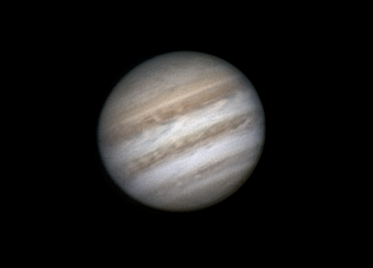
I have not done much planetary work with this camera, but yes, it will deliver:
This was taken with RC8 scope - larger secondary obstruction, and hardly planetary instrument - but still works good enough
-
1
-
-
Don't know about UK, but here it is in Germany?
They have a number of different adapters so you can have a look if that is what you need (pictured above is 2" / t2 both female threads as far as I can see?)
-
1
-
-
You are rather limited in your budget and requirements that you listed (planetary, lunar, solar, EEVA) although at first look similar, have some differences that make choosing camera very hard task to do.
I will start by listing things requirements for all types of imaging and then we can see how any particular camera model suits that.
- all of these require camera that has low read noise and high quantum efficiency, so that is common thing
- planetary, lunar, solar require fast download rates (meaning USB3.0 camera, ROI capability for planets, high FPS in any case)
- for planetary it is easier to work with color sensor (limited budget, no need for filters, filter wheel, and recording with change of filters is a bit difficult).
- for lunar and solar due to lack of color - mono sensor is better option. For H-alpha solar it is much better option (although color sensor can still be used - it will be only 1/4 effective since only 1/4 of pixels register that wavelength - red pixels).
- for planets you are fine with very small sensor - something like 1/3" sensor
- for lunar and solar, you want larger sensor, but not too large. Well, that depends on what sort of telescope you have. It needs to have diffraction limited field large enough to cover sensor. This is not a problem for smaller sensors, but could be problematic on a larger sensor like 1" sensor. If you attempt to shoot full disk images or mosaics - you don't want your images/panels to be soft at the edges because scope is no longer diffraction limited there.
- For EEVA mono is better than color in terms of getting image on screen quicker - more sensitive, but color provides you with color of object - something that is interesting with stars / clusters and nebulae (planetary in particular).
- For EEVA you want your sensor to be as large as possible or you need a scope that can be reduced well (by reduced - I mean focal length reduction).
- cooled camera will only be beneficial for EEVA (although many people work with non cooled cameras, having set point cooling, even if you don't use sub zero temperatures - enables precise calibration, which is beneficial).
Now we can begin comparing sensors
If I go by your signature and conclude that you have Skymax127 and AA 72ED-R, and want to do everything equally well - I would say go for 178 - color model.
For that camera and Skymax127 you will need x2 barlow to get to critical sampling rate (for color camera). Since it is Mak, I doubt you will be doing Solar Ha, so color model is fine - for lunar and planetary it is fine as well.
For 72ED-R and EEVA, you will benefit from focal reducer, although you don't need field flattener. Something like x0.79 FF/FR will make that scope into F/4.8, but even better would be GSO x2 simple reducer (1.25" version, you don't need full 2") - mounted to give you something like x0.66 reduction to make your system F/4. You could try to use it at full x0.5 and F/3 but I believe your edge of field will suffer greatly - that small scope has quite a bit of curvature due to short FL.
In any case, for EEVA with said x0.66 reduction you will have 1.77"/px system (very good for AzGti mounted scope for EEVA) and following FOV:
That is ~ 1.5 x 1 degree field - quite good.
In any case - you have "tools" to decide now, but if you have any more questions - just shoot.
-
1
-


M42- processing is a skill (I ain't got!)
in Imaging - Deep Sky
Posted
Here is the best I was able to pull out of this data:
Hope you like it. I'll do another step by step tutorial later to explain how I managed to process the image like this.
It's going to be a bit more involved tutorial - it's a bit "advanced" stuff as it includes another piece of software (also free as gimp) and plugin that I wrote for it (background removal).