


JamesF
-
Posts
31,960 -
Joined
-
Last visited
-
Days Won
182
Content Type
Profiles
Forums
Gallery
Events
Blogs
Posts posted by JamesF
-
-
Woohoo! Rain gauge reassembled to the point of being able to test it with the new reed switch and battery pack, and it appears to count "tips" without a problem. When I unplug and re-plug it, the existing counter values are retained as well. Excellent news
")
So, tomorrow I shall completely reassemble it and make sure the calibration is correct by dripping water in from a syringe. Once that is done I reckon it's ready to go back up.
James
-
 1
1
-
-
It never rains but it pours, ho ho. It seems that this evening my air pressure sensor has started throwing a fit as well

Up to about 4:30pm I had a pressure reading of about 1034 mb and temperature of 7.18C which is a bit high, but then it always reads about 1.5C high. Then it started going crazy and producing figures like -152.52C and 717.4 mb or 314.67C and 1643.4 mb interspersed with values that look fairly normal.
It could be that for some reason it's not happy about the temperature which is currently down below 2.5C for the first time in ages, but that wouldn't be helpful. Still, I'll worry about it after I have the rain gauge sorted.
James
-
Well, I ran out of time this weekend. For the best of reasons though, as we spent much of Sunday catching up with friends we've not seen in a fair while.
I ordered some tiny round neodymium magnets (1mm deep by 2mm diameter) and I think my first experiment once everything is reassembled will be to add a few to the end of the existing magnet to see if that helps things at all. Having had little experience with reed switches it's interesting that the magnet has far more effect at the ends of the switch than it does in the middle.
I couldn't find any holders for a 3V battery (something like a CR2032 for instance, which we usually have plenty of) that looked suitable and weren't going to take six weeks to arrive from China, so in the end I bought a holder for some AAA batteries instead. I reckon there should be room for that inside the sealed compartment that contains all the electronics.
That's my evening sorted then
James
-
19 minutes ago, Oldfort said:
I'm just one short of the full set of Apollos.
That so sounds like a euphemism. Like "one sandwich short of a picnic" or "one can short of a six-pack"

James
-
2
-
 1
1
-
-
My reed switches arrived today. They're the same size as the original to within fractions of a millimetre, but after connecting one to a multimeter it's clear that the existing magnet struggles to trigger it. I've ordered some tiny neodymium magnets to see if they can do any better.
James
-
I don't remember that one, and I, err, wasn't two
James
-
2
-
-
I think that's consistent with my understanding at this point, Malc. Hopefully I should have some new reed switches arriving today and with a bit of luck I might find the time to reassemble everything and test it over the weekend.
James
-
Another kind offer, thank you. I've got a few on order now though, so as long as I don't break loads trying to replace the existing one then I should be good
In the case of this rain gauge, the magnet is at the top of the wall between the two buckets and the reed switch placed such that the magnet passes it as the bucket tips from one side to the other which I think is the last of your options. I guess that makes sense in that when either of the buckets is filling, the switch is inactive because there's no way to know how long it will be until the next tip.
I don't particularly like that the magnet is inside a plastic housing on the bucket see-saw and the reed switch is inside another plastic housing sealed away from the water. It's not a very powerful magnet (about 3mm in diameter and 5mm long) and putting possibly as much as 3mm of plastic between it and the reed switch doesn't seem like it would help reliability. I have toyed with the idea of putting a neodymium magnet in instead, but of course the risk then is that the switch is always activated
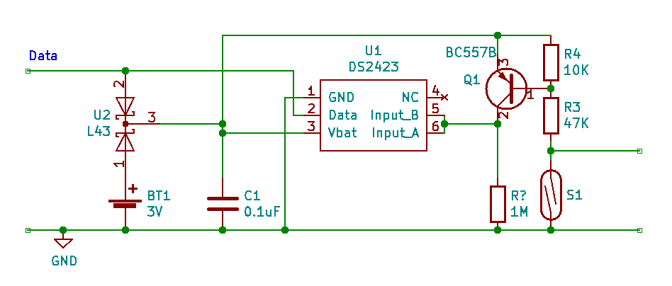
For completeness, I'll add my attempt at the full circuit diagram for the board here as well (may not be entirely accurate as I've drawn it by following the traces on the board which are not always clear.

James
-
I've had a fun evening playing with KiCad, and this is what I've come up with for the full circuit diagram of the board. I can't deny that it's something of a mystery as to why there's a resistor labelled "R4" when I can only find three of them.
I should have designed the DS2423 part so that pin 1 was on the bottom, pin 2 on the top and pin 4 moved to the left side. It would have looked neater. Never mind...
The connections on the left are data and ground on the 1-wire bus. Those on the right are just a couple of pads on the PCB that would allow a second switch to be added for testing I think.
I've realised that the reason the 3V battery only keeps the memory in the DS2423 alive and doesn't allow the counter inputs to work is because the power for the counter input circuitry is taken parasitically from the Data line inside the chip, so if the 1-wire bus loses power then there can be no power for the input circuitry.
James
-
8 minutes ago, PeterC65 said:
What surprises me is that they didn't just put the reed switch where the transistor is and then dispense with the rest of the circuit apart from the 1M resistor!
That's pretty much what the Dallas version of the same unit does. I don't understand why there's the additional complexity for this one either.
James
-
Ahhh, I wonder if there's something more complex going on here that I'd not got my head around.
I'm assuming 3V because there was a 3V battery used, but I wonder if that isn't sufficient to trigger the transistor, yet is sufficient to keep the counters valid in the counter chip. So should there be a long-term loss of power from the data bus, no more pulses could be counted, but those already counted would not be forgotten. Perhaps given that 3V button cells are easy to fit into small spaces the designers decided that not losing historical data was desirable whilst not missing data during a power outage was too much of a pain to do.
If the data bus/Vin were at 5V (which may be possible), then with the switch open the base would be at 5V and the transistor would not conduct, so the output would be 0V. With the switch closed the base voltage would be about 0.88V, I think.
Thanks for pointing out that I'd forgotten how PNP transistors work, btw. I'd completely missed that
James
-
1
-
-
I definitely have a different circuit as there's no DS2407 on mine. I think one is based on the other though, so it may well be reasonable to assume that the reed switches work the same way.
James
-
It's entirely possible I have it wrong as it's not at all clear where some tracks go. I'll have another look. I'm fairly sure about the 1M resistor though. It's an SMD resistor with "105" printed on top. That's 10x10⁵ ohms, isn't it?
James
-
Related to another current thread of mine, though it's probably not necessary to read it:
I'm trying to understand how the electronics work so I can determine whether the reed switch is normally open or normally closed and replace it with the correct type. Whichever type it is, it is used to generate pulses as a magnet passes it on a random basis.
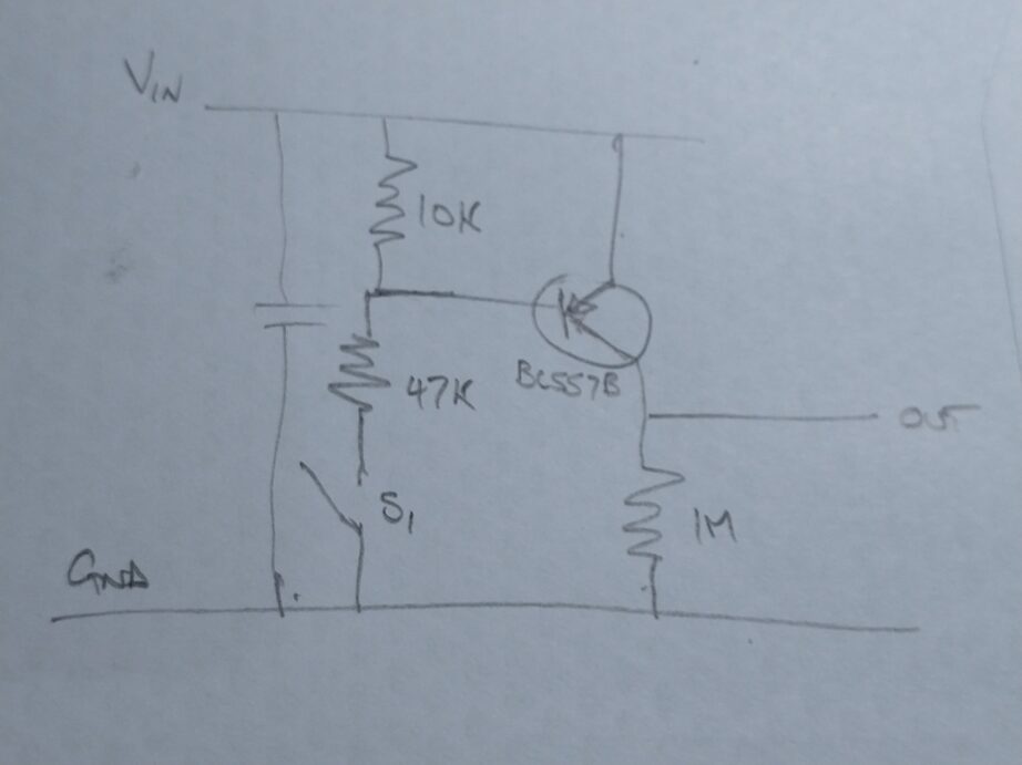
I've spent a happy few hours chasing stuff around the circuit board and I think the relevant bit of the circuit is this (in proper engineering fashion, it is genuinely on the back of an envelope):
"OUT" goes to the input of a 1-wire counter that counts hi-to-low transitions of the input. I think the capacitor is just because 1-wire uses parasitic power. That is, the supply voltage is actually taken from the data line (which may be connected to ground during signalling) and the capacitor just acts as a rechargeable battery when required.
So I'm thinking that if Vin is 3V and S₁ is open, the transistor's base is at 3V, and OUT is also connected to 3V. If S₁ is closed then 3V is divided across the two resistors, leaving the base at about 0.64V. That's probably not enough to cause the transistor to conduct though I don't imagine it's that far short, meaning OUT is 0V. Which in turn means that closing and re-opening a normally open switch will generate the required hi-to-low leading edge transition for the counter. Regarding the voltage, there is a 3-pin SMD package on the circuit board that I think may be one or more zener diodes. The package is labelled L43 and there are no other clues, but perhaps they might be working as a voltage regulator to make sure Vin is not greater than 3V? And perhaps even if the transistor does conduct a little, it may not cause a sufficient change in voltage to register as high at the counter input?
Opening and then closing a normally closed switch would generate a hi-to-low transition on the trailing edge of the pulse I guess, the difference being that the input would float low rather than float high. Perhaps there's something about that in the DS2423 datasheet.
Does that sound sane?
James
-
Hmmm. I've just found a datasheet for the DS2423 which says that the counters increment on a low-going edge, suggesting that the reed switch may be "normally closed" after all, or that somewhere there's an inverter in the circuit. At this point I think a circuit diagram would be helpful.
James
-
47 minutes ago, ollypenrice said:
Death by drowning.
I guess all that water explains why they use a reed switch, eh?
James
-
1
-
-
Oh dear
I just attempted to gently straighten the leads for the reed switch a little so I could get a better view of the mechanism and the glass of the switch came apart as soon as I touched it. I suspect it may have already failed and my attempting to move it was the last straw. If I can't find a circuit diagram online then I think I'm going to assume it must be a "normally open" switch. I'd guess that if it were normally closed then current would be flowing somewhere all the time which doesn't seem like a good decision for a 1-wire device.
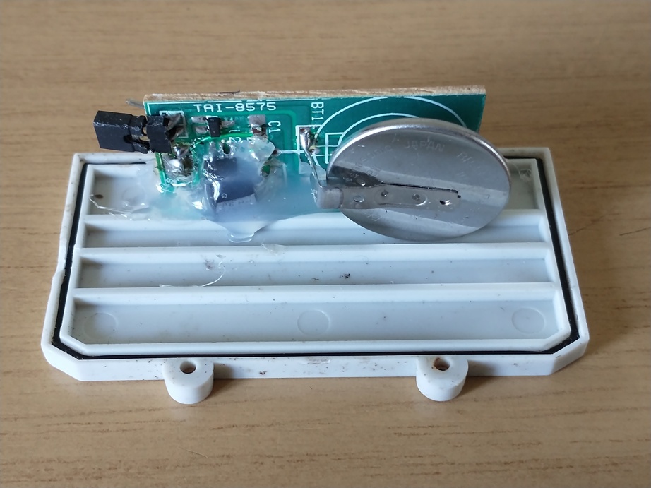
Having had a better look over the PCB with a magnifying glass I think "TAI-8575" might be the part number for the entire thing. The 1-wire counter itself looks like it is probably a DS2423 which I don't believe has been manufactured for years. If I can't get it working with a replacement reed switch then it looks like I might have to try something along the lines of replacing all the electronics (perhaps using an Arduino?) in the existing hardware and find a different way to get the data onto a PC.
James
-
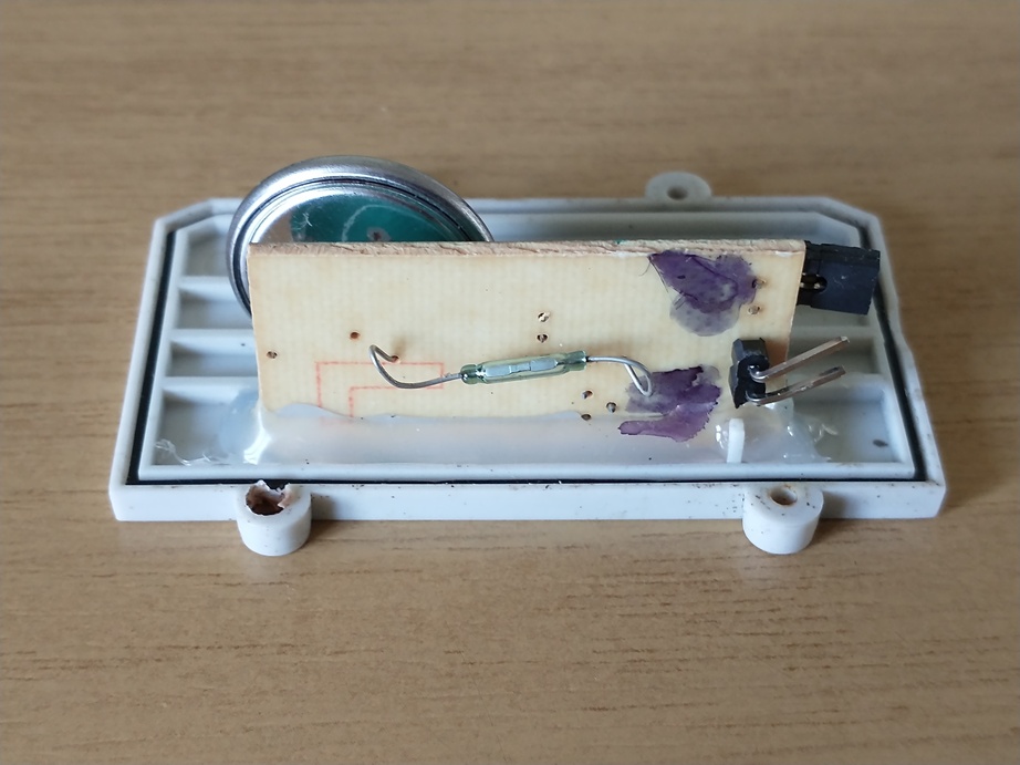
Ok, so this is the reed switch:
The two-pin header is my later addition, as it allows the board to be disconnected from the cable, which was originally soldered straight into the PCB. Most of the components are on the other side, buried under a load of hot melt
Even the battery terminals are welded directly onto the battery itself. No expense spent
Fortunately the battery is only there to preserve the counter values in the 1-wire chip over a loss of power. I can live with that sort of failure I think, though replacing it with a proper battery socket does quite appeal.
The circuit actually looks quite simple and I'm half-tempted just to rebuild a new board from scratch but for the fact that I can't find anywhere selling the TAI-8575 any more and if it were surface-mount I'd still not be able to do it, so I guess the first job is to peel off the hot melt, and then try to work out if the reed switch is actually intended to be "normally open" but is stuck closed, or if it really should be "normally closed". I think I need to find a magnet...
James
-
1
-
-
16 hours ago, Budgie1 said:
I don't know if the reed switches get sticky over the years but, as I say, I've at least one reed switch go bad in an anemometer and thump on the pole was enough to free it for a while. This one kept sticking so was replaced in the end.
Now I have mine on the desk and opened up it looks as though the reed switch might also be stuck closed. There are further complications though
I'll post some photos later.
16 hours ago, Budgie1 said:I've still got an iButton DS9490R here, along with an old Hobby Boards Solar Sensor.
If they're of any use then PM me your address and I'll pop them in the post. No charge, I've not used them in years so not sure they still work. Although the DS9490R is recognised when I plug it in to a USB port.
That's very kind of you to offer. I can certainly put them to use as it would allow me to have two 1-wire channels and I always wanted to add a solar sensor. I'll PM you.
James
-
Ah, yes, HomeChip might be worth a go. I ran out of time to dismantle the rain gauge before it started to get dark, so I guess that will have to be a job for tomorrow. I did at least find my spare DS9490R, so I don't have to disconnect everything else to be able to test it.
I assumed the reed switch would be normally open and therefore unlikely to fail closed, but I guess it's possible.
James
-
For many years I've had a 1-wire "tipping bucket" rain gauge sold by AAG. I gave it a service a couple of years back and made a "crown of thorns" to stop birds perching on the edge of the funnel and, err, blocking it up. Until the last month or so it has worked very nicely. Now however it appears to have died completely
The 1-wire device still shows up in Linux and is readable, but the 1-wire counters never change. I've checked by dribbling water into the funnel from a jug and the buckets tip, but there's still no change in the counters. The circuit for the system is quite simple as far as I recall, being little more than the 1-wire counter chip and a reed switch in a housing next to the buckets, with a magnet fixed to the buckets tripping the reed switch each time the bucket tips.
It could be a failure of the 1-wire chip, or (as I suspect is more likely to be the case) the magnet is not activating the reed switch for some reason, perhaps because it passes the reed switch too fast. I have thought about trying a different, perhaps stronger, magnet, but finding one of a suitable size and weight looks like a bit of a lost cause.
I could throw in the towel and buy a new rain gauge, but they all seem to want to come with displays or be wireless or other stuff I just don't want, with a price tag to match.
I'm about to disable it in the software and bring it inside to see if I can do anything, but at the moment I'm not feeling very hopeful
On the other hand, if anyone knows of a simple rain gauge (I don't need any other sensors, wireless or a display) that connects to, say, a Raspberry Pi, either complete or DIY, pointers would be gratefully received.
James
-
Wikipedia says it is pronounced "-zoo" or "-soo". I thought it was "-so", too.
James
-
1 hour ago, EarthLife said:
es indeed, though I want to ensure that the routines are fast enough to keep up with rotation. If the motors start rotating at a fast rate then the software only has to keep track of the coarse printed graticule scale, it's only when rotation slow down that the firmware will use the sandpaper pattern to fine turn the exact position computation.
It's more complexity in the design obviously, but you could even have some sort of very simple coding for position (Huffman?) just to allow you to identify, say, which eighth or sixteenth of the wheel you're looking at to be easily able to cut down the search space for the sandpaper if you've lost track of where the graticule scale is.
James
-
1
-
-
I have been wondering about the process of identifying the axis position.
It strikes me that it could be not at all dissimilar to identifying the location that a camera is pointed at from an image of the sky, by treating the bright points from the sandpaper as "stars", in which case perhaps much the same algorithms might be used? Hopefully in the case of the sandpaper the search space would be considerably smaller.
James


My rain gauge has died :(
in DIY Astronomer
Posted
And to calibration...
My gauge appears to measure 112.5mm in diameter (just under 4.5") which is a bit on the small side I think. I guess it wouldn't be that hard to fit a larger funnel if I wished though. A bit of research suggests that a diameter of 8"/200mm is considered reasonable.
Anyhow, I calculate the collection area of my gauge at 9940mm². Dripping water into it from a syringe suggests that the bucket volume is something very close to 2.5ml, meaning that each tip would represent 0.25mm (ish) of rain. Within the level of accuracy I'm able to achieve it therefore does look as though each bucket tip probably measures 0.01" of rain (I think most of this stuff was intended to be used for imperial measurements).
And now it's time to get the step ladder out")
James