


Stub Mandrel
-
Posts
10,662 -
Joined
-
Last visited
-
Days Won
32
Content Type
Profiles
Forums
Gallery
Events
Blogs
Posts posted by Stub Mandrel
-
-
18 minutes ago, markse68 said:
A piece of orange Formica 😊

You win the 2020 Turner Prize.
-
 1
1
-
 6
6
-
-
1 hour ago, HollyHound said:
Yes, good point... still originated here I suppose 😊
ARM stands for 'Acorn RISC Machine'.
Acorn built the Electron and the original BBC Micros and the original ARM processor was produced as a co-processor for the Beeb.
It's fair to say that the most ubiquitous computer processors in the world are a direct evolution of the BBC Micro. Beat that, Microsoft and Apple!
-
2
-
1
-
-
Took me numerous sessions to get that much M101 with a dslr. It's not an easy target.
-
1
-
-
20 hours ago, fozzybear said:
Neil,
how's the project coming along and what scope are you planning on using it on?
Andy
Hi,
The electronic bit Just Works (TM)! Fire up Sharpcap and it does everything you expect, even moving rapidly then slowing down at the end of a long move. Only thing is it was a tad slower to respond than my ZWO EAF, presumably because it uses a smaller stepper with a bigger gear ratio. I changed the stepper speed settings in line with Dave's suggestions to tune it up to be a bit faster.
One thing that's interesting is it happily runs off the 5v USB supply with no 9V battery fitted. It will only draw about 145mA even when two coils are energised, so this should be fine - there's plenty of torque.
I need to make a fixing bracket and adaptor, to be honest the only thing holding em back is it's the ED 66 scope I made myself and I'm reluctant to remove my lovely home-made knob!
-
1
-
-
I found this.. the little blur diagram looks a bit like the distorted stars..
-
On chromatic abberration this is what I figured...
If you use an RGB sensor and have CA some colours are out of focus, so you get halos.
If you use RGB filters with a mono camera all your subs will be sharp, so no haloes.
BUT the focal length for each colour will be slightly different so the image scale for each colour will be different.
Say the blue focuses further away from the lens, then the blue image will be smaller.
This means that in the composite images there will be blue fringes on the inside edge of the stars in the corners, and the outside edge will look yellow.
I'd expect bad alignment to cause a consistent shift in the same direction across the image.
That said, having seen the odd star shapes Ken's getting, I think it's one or more lens elements out of alignment, so hopefully fixable on an optical bench.
-
1
-
-
15 hours ago, Piers said:
The screw that sticks out of the tube rings, I think it's for mounting a camera.
Has anyone been able to remove it?
It looks like it should just unscrew, but I've tried and so far no luck.
Take the ring off, it unscrews from the other side 🙂
-
In a very dark room, white wall lit from a shaded lamp (with a hoodie over the top!) 4m away:
Camera 6 seconds, f3.5, 800 iso. Formula gives a value of 0.0319.
Meter varying between 0.0133 and 0.0128, but pretty clearly centred on 0.0130 Lux (correction factor set to 1.0).
Comparing the first figures were 0.39 and 0.22, ratio 1.773.
Second figures 0.0319 and 0.0130, ratio 2.454.
That's a significant difference BUT the second experiment was done under much more consistent conditions.
I'll put the 2.45 ratio into the device and then see how it measures up against real skies in due course.
-
12 hours ago, Legion Of Andromeda said:
gave it a lick of paint
Sammy Hagar fan?
-
1
-
-
22 hours ago, g-rex said:
But I'm having fun, and when I can afford that Heq5 then I'll have already made all my mistakes, I hope.
🤣
Worked for me... not!
-
1
-
-
Cheapest way in if buying new is a Star Adventurer used with existing camera and lenses.
The pro pack is about £270, but you can get by with the standard pack.
Later it has enough oomph to take a small refractor.
I actually started astrophotography with a 150PL - a long reflector, on a manual EQ3 tripod (£180 second hand) to which I fitted an RA drive (home made) but you can buy one for less than £100. I was able to do 30-60 second exposure unguided although a proportion were trailed.
Not ideal, but the long scope meant that a field flattener or coma correcter weren't needed. I got results that made me want to achieve more, so I bought a s/h 130P-DS and ended up fitting the EQ3 with RA and DEC and basic goto/guiding. With guiding I was getting up to 5 minute subs even with an EQ3.
Personally I would recommend the 130P-DS over a frac for a beginner in AP, with the SW coma corrector its 'plug and play', collimation is easy after the first time. With my frac there was a long sequence of test runs to get the field flattener spacing OK.
Next I got an HEQ5 mount, again s/h.
Then as ASI1600 mono camera, again, s/h.
Each step has seen my results improve, but also each step has been really rewarding. Buy deciding what I wanted and then waiting for good s/h examples I built up my kit for significantly less than buying new.
I still use the 150PL - I've been suing it exclusively for the last few months building up my collection of messier galaxies and clusters.
So it can be cheaper than you expect, but there is always the urge to go for the next upgrade!
-
1
-
-
Wowser!
"Build 'em big!"
-
2
-
-
The curved brass rod approach is so simple and obvious - once someone else has thought of it first!
Well done! Most impressive.
-
1
-
-
If funds are tight, you can do astrophotography with an EQ3, although having upgraded the HEQ5 makes life easier, simply because it is less 'fussy' about tuning and adjustment.
-
2
-
-
Good luck Ken, hope it comes back cured from its trip to Lourdes...
-
1
-
-
2 hours ago, Chriske said:
Could explain this a bit more in an assembly drawing please, not sure I understand, sorry...
Photos will make it clear when I have some!
The sector is normally modelled on a section through an imaginary cone with its axis pointed at the pole and its lower edge horizontal. To create a bearing surface, the sections are typically extended into short prisms of constant cross-section.
A section at 90-degrees to the cone axis is circular.
- Its contact point (where you would place a roller) is stationary as it rotates (convenient, allows rollers to be compact).
- Its bearing surface is angled to match the elevation of the pole star (awkward, and easy to lose position/drive).
A vertical section is elliptical.
- Its contact point moves towards or away from the pivot (cone apex) as it rotates (awkward, requires longer rollers).
- Its bearing surface is horizontal (convenient).
My idea is for the section at 90-degrees to be extended as a short truncated cone - a true slice of the imaginary cone.
- Its contact point is stationary (convenient).
- Its bearing surface is close to horizontal (horizontal at lowest point, a few degrees for practical sector designs) (convenient).
-
1
-
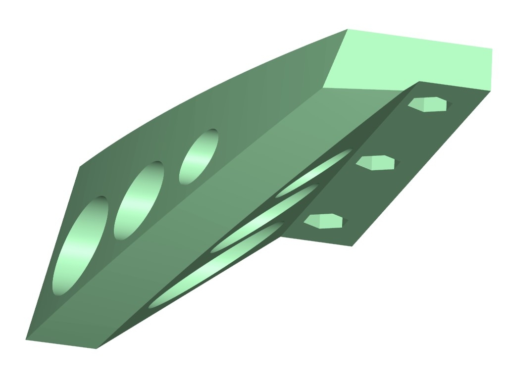
TLDR: I found that arrangement very critical in term,s of positioning and worried that the PLA might 'creep' so I lost drive. Instead I've come up with an arrangement more tolerant of my woodwork skills!
I've had a rethink!
The problem with the angled sectors is that although they have a simple, circular cross section is it makes the positioning of the support/driving rollers critical. I found that this made getting a good drive to the sectors difficult, and a slight twist (just a couple of mm) in the board was enough to make a difference.
I'm also wary that the PLA could 'creep' under a sustained angular load despite the hefty design.
The elliptical design avoids this by having a vertical load but needs long rollers as the contact point moves in and out.
An ideal design MIGHT be to make the sectors part of the surface of the 52-degree cone so they track across the same point like my original angled sectors, but can use almost horizontal rollers angled in line with the pivot point.
Hard to do in wood without a 3D jig but easy in CAD. The front curve of this new runner follows the same curve as my MK 1, but instead of havinga steeply angle rolling surface it has an almost horizontal one. It also means the upper surface can be supported by the upper board, even though the fixings will be set back. Importantly, as the load will all be acting vertically that small twist in the board effectively becomes irrelevant as the position of the rollers is no longer critical. Instead of having to set them so the sector falls at the right place on the roller, the roller can be made over-length without any criticality in positioning. Finally, almost all the weight of the scope will be keeping the roller in contact with the sector instead of about 60%:
The downside is that it means the aluminium strips may not be feasible. I can get a decent surface finish without steps using careful orientation and support material (on a non-working surface). Any residual irregularities will, hopefully, be too small to cause problems and partly compensated by give in the rollers.
-
1
-
-
That's interesting!
A rough and ready try with the camera gives me 0.127 cd/m^2 for the dark inside of the bottom shelf of my 3D printer stand.
The SQM gives me 0.39 Lux with the lens, but that's with a 'correction factor' of four so the actual reading (it bounces around a bit) is 0.10.
Without the lens it's reading 0.89 Lux, so 0.22 uncorrected.
Clearly 0.127, 0.10 and 0.22 are all in the same ballpark, the difference between 0.127 and 0.100 is 0.3 magnitudes.
It looks like spending some time tonight when I can get a more consistently illuminated surface sorted out it will do as an initial calibration.
-
I've found this, which will let me get a value using a DSLR:
https://www.translatorscafe.com/unit-converter/en-US/illumination/1-7/lux-candela steradian/meter²/
Reflected light
Determining exposure by means of measuring light reflected from the object using a light meterFor light meters that measure reflected light, the camera settings (f-number and shutter speed) are related to subject luminance and ISO speed by the following incident light exposure equation:
N2/t = LS/K, (2)
where
- N is the relative aperture or f-number
- t is the shutter speed or exposure time in seconds
- L is the average luminance of the scene measured in cd/m²
- S is the ISO speed (100, 200, 400, etc.)
- K is the reflected light meter calibration constant; Canon and Nikon use K = 12.5.
So I can let my DSLR calculate exposure for a dim, evenly illuminated surface and calculate the luminance with:
L = N2/t . K/S
-
I can probably set something up with the ASI1600 but I don't have a calibrated lens combination. I could try and calibrate from a sub with eth 130P-DS or 150PL but that's abit clumsy to move to the living room...
I think I may just be patient and wait for the next dark evening.
-
That method makes sense, but not easy at the moment.
One way of calibrating could be to use a light source with known luminosity. The problem is standard LEDs have all sorts of variation, but it must be possible to make one...
The sensor library calculates a reading in Lux and as 1 lux = 1 cd/square metre, so you can calculate magnitudes/square arcsecond directly from this.
The formula from unihedron's website works (e.g. a reading of 0.0002 lux gives 19.83).
While this is uncalibrated the sensor goes past mag 22 before it reads 'infinity'.
I noted a few things last night:
You had isn't opaque enough to block all light!
If you do block all light successfully you get readings of mostly 0 with an occasional 1 for both IR and Full spectrum. This is impressive as the data sheet says it could be up to 20. I've added potential for dark subtraction but set the numbers to zero.
The lens appears to have a real world FOV of about 30 degrees (measured by seeing when and obstruction reduces the reading)
The lens has about 0.4 times the response compared to a tube giving about an 80-degree FOV.
This is quite a lot more presumably than you would expect with a smaller field of view.
Even with a fairly bright but starry sky last night (about 11:00pm so two hours before the moon was at zenith, pointed at the Plough area) it was reading about 19.8, so realistically under-reading by a few magnitudes.
The readings definitely show variations. Assuming these are essentially random (due to thermal noise, motion of the sensor etc.) this opens the possibility fo using over-sampling to improve resolution at low levels.
For a trial I'm using 4x oversampling and in conjunction with an estimated correction to the Lux reading.
It all works and gives believable readings but I need to calibrate properly.
-
I've made a basic SQM using a TSL2591 and an arduino nano. I'm aware of its limitations but I'm not too concerned if it looses precision at the ~0.002lux end of the scale - if the sky is anywhere near that end of the scale i won't have anything to worry about!
At the moment it is just reading Lux on the longest integration time/highest gain using the Adafruit library.
I plan to take dark readings for both photodiodes and subtract these before calculating lux using the Adafruit library routine.
I realise that calibration is not particularly important except for comparing with other people's readings.
The obvious route is to get a reading against an existing meter or at a location with a good estimate using Clearoutside or similar, but the latter requires a good clear night with astrodark....
I was wondering if there is an alternative way of calibrating, such as using a camera to take pictures of a plain wall in a dark room and calculate the from the image data while taking simultaneous readings with the meter.
Has anyone tried anything similar and can they give advice of calculating magnitude/arcsecond squared with a camera?
This is a lash up - the lens mount (its an ex-binocular eyepiece) is too long and being reprinted, followed by a better version of that light shield.
P.S. I'm probably going to add temperature compensation later, but that's down the road...
-
1
-
-
10 hours ago, Anthony1979 said:
Well was hoping my SW 130pds was going to arrive... Was suppose to be here yesterday but phone and they said its coming today but not holding my breath.... Unhappy...its looking like a refund
Delivery times are totally random at the moment. I've had things arrive almost next day and others take weeks. Apparently there are parts of the country that are acting as bottlenecks.
-
Progress... and some miscalculations...
The platform is materially complete (aside from levelling screws and the electronics). The good news is the 3D printed pivots appear to be strong enough.
I mounted the scope and found two problems:
- The scope starts to tip when it gets near the final extent of its travel.
- The roller doesn't have enough grip to move the scope at this point as the load on it become 'light'.
I have realised this is down to two things - surprisingly not my C of G estimates (which tipping the scope on its base showed to be fairly close to correct).
- I've made my sectors far to big! The platform can tilt through over 33 degrees, typical platforms rotate through just over 15 degree to give an hour's tracking. It's taht extra tilt that's the root of the problem
- The scope is pivoting on its teflon pads, rather than on the rollers which are further apart. Tightening the bearing would help BUT would then make the azimuth adjustment too stiff.
Two solutions, one of which is obvious:
- Restrict the tilt to around 15 degrees by fitting stop switches.
- Use four teflon pads, to give the maximum width of support for stability, just in case.
-
1


Equatorial Platform - New Build
in DIY Astronomer
Posted
Here we go, these are the new rollers. You can see they are a much simpler shape and how the 'new' sectors allow them to be horizontal. Instead of a precise location, they just need to be placed in contact with the supported and unloaded platform and slightly angled to get line contact and avoid any risk of the sector hitting the box.
I've decided to stick with the simple 5: ratio for now,as slightly smaller rollers will give me a step size of about 0.016m and I suspect that for a simple platform rather than a precision engineered mount a resolution smaller than this is pointless.
At my sector diameter of 788mm, one arc-second is almost 0.002mm, so I will have 8 arc-seconds per step, 550 milliseconds per step.
Obviously these are best estimates to be fine tuned in use. I will be able tune to +/- 0.2% using the millisecond counter in Arduino.
The new parts fill the old upper platform but it doesn't take advantage of the extra surface on the new sectors:
I'm going to make a new platform, with a more rounded shape that will also allow me to move the pivot point further forward again. I will be getting close to the axis through CofG ideal by accident rather than design!
I've just got to wait for some ball races to replace the ones I lost for the tension idler.