


Chriske
-
Posts
1,425 -
Joined
-
Last visited
-
Days Won
1
Content Type
Profiles
Forums
Gallery
Events
Blogs
Posts posted by Chriske
-
-
Change of concept.
The first tripod I designed was a bit flimsy. It was perfectly ok to hold a smaller scope. As a matter of fact it would have been overkill for a smaller scope I think.
That bino as it is now weigh 10kg (about 20lbs) and I still need to add optics and worm/wormwheel unit. The main pier of that new mount is 270mm in diameter. I added two somewhat thinner branches to make a sturdy triangular construction.
Weight of that tripod 35kg (about 70lbs) It is not only heavy but sturdy and very stiff as well..!
Busy painting that base-platform now.Next step is add a drive system to the mount. I was planning to install steppers and OnStep software, but I might go for a simple azimuth mount + equatorial platform

-
 2
2
-
-
Oops...!
Forgot to turn one primary cell 90°. silly me...🙄 Will correct that tomorrow.
That 90° rotation has to do with last minor corrections to images overlapping 100%.
This minor correction is absolutely necessary to avoid strain in the eyes/brain during observing.As a matter of fact the brain does correct very small misalignments of both tubes during observing trough a binocular.
On the other hand it's in fact amazing how much the brain is able to compensate misalignments. Done some tests in the past how far I and other people can go while turning one bolt, left or right of my binoculars. You actually can feel the moment the brain 'gives up' while turning that bolt. When it happens the images pops out of alignment in a split-second. When that happened the images are very far apart. Very strange.
You can only do this ones or twice because if you do this trick to often you end up with a splitting headache.Talking here about misalignment I'm talking telescopes not exactly parallel, not misalignment of the scope(s) optics itself.
-
Rusted, Victor,
What a coincidence, Wieth Knudsen...!!, I met the man 40 years(or so) ago. He was a well known observer. We invited the man at our observatory Urania (Hove-Belgium). He gave a lecture on occultations.
-
1
-
-
Final assembly, optics not finshed yet.
-
7
-
-
-
Good idea...!
And indeed interconnecting them is an absolute must. -
That is a combination of science, art and skill...

I'm drooling man...!!!-
1
-
-
And these are extra flat baffles that will be installed between the baffles shown in the picture here above.
Holes in these baffles is 50mm.
The inner diameter of that first flat baffle (seen from the secondary mirror) should be correct. If the diameter is to small it will act as an obstruction to the incoming light, ending up with darker images. If that diameter is chosen to large, direct light from the Moon will enter at a shallow angle into the secondary tube. It needs to be perfect. When it is, these scope deliver high contrast images.-
2
-
-
Thanks for the kind words,
And one more thing Tony, I forgot to mention here above(mentioned it somewhere else before if I'm not mistake).
I never, ever, use dark colours printing telescope-parts if that scope (or other project in the garden) are exposed to the sun.
Did some thorough tests with printed parts, in different colours, in the past. White filament (even PLA(!)) is the absolute winner whenever these printed parts are exposed to the sun for months in a row. Needles to say black is the big loser here. It deforms and sags enormously in the sun.The inner surfaces of all my scopes and parts are painted black of course.
-
Hey Tony,
Thanks for the info.
To be honest when we first started working and investigating the possibilities of 3D printers we were not planning to do the things I do right now.
About 6 years ago when we made our first we were eager to find out what we could do with these 'toys'(as my my wife used to call it). Nowadays my wife don't call it no more 'toys for boys' as she very often ask me if I could repair or even make items to be used in combination with her own hobby(s).
Anyway, I'm always pushing things, see how far I can go(story of my life... ). As a mechanical engineer I do have a good idea how things should be built strong and most of all very stiff.
But in this case, working with printers, (making plastic parts) it is a completely other story. I have to 'reinvent' again all the techniques I am familiar with. I do design all projects myself. One of he first things I had to learn was how to make printed parts as strong as aluparts. First rule : NO slim-line parts ever..! Second was the major advantage compared to classical (mechanically) made parts : all parts that has been drawn can be printed. Even the most complex parts are printable...! Not feasible, using the most sophisticated CNC machines. I do have discussions about this with other CNC(mill) users, until I show them a few parts I printed, asking if they’re capable of making that in aluminium. Not..!
But..! I always combine printed parts with metal or alu parts. There's no way I print an entire scope just using PLA(or whatever). I carefully combine metalwork and printed parts. In fact the major structure as in this project, is 3 alupoles mounted in a shallow triangle. These poles are the basis of the scope. When I print a few parts for holding these poles tightly in place, I can do whatever I want to finish it of with printed parts to make a scope out of it.
The primary cage of this Greg. has 6 separate parts bolted together with M6 bolts. Additionally : inside the mirror-cell are a few long 8mm rods(not visible) to make things very stiff. I can assure you Tony there's no way that thing will sag or bend.
Yesterday I reprinted the secondary cage because : not stiff enough at all. So this is the one I'll be using now.
On the left the old and on the right the new secondary cage. The new one has the same wall-thickness and is very stiff. (I still need to remove a few burrs and some stringing, I know...)
To be clear on the matter. This new circular 'spider' is very high. I can use this high version because this scope has a very narrow TF(focal length 6(!)meter). If it were a short(er) focus 'light-bucket' I would not go for this solution of course. I'd probably go for a completely other setup to build that secondary cage.-
1
-
-
Just finished printing live size(almost) 'first step'. 300x200mm. Print time 39 hours. When it was about half way printing there was a glitch. Printhead shifted a few millimetres sideways...DAM...!
Something went wrong during slicing imo.
I printed lots of Bino parts, Marc's Gregorian telescope parts, four 2 meter high SaturnV rockets + some other smaller projects for my wife. NEVER had any problem at all during printing, all my prints were perfect and now during that long print I got this glitch...DAM again..!!(sorry guys). -
Thanks guys for the kind words.
Borrowed an adjustable reamer from a friend to clean up all the holes for these poles.
-
1
-
-
I know the alignment is very critical in these scopes. But again I did not print these parts slim-line. That's why.
Although I could do a stress analysis in Inventor I did not preform it because there's no need to. In the past I made a few of these scopes, even single pole-scopes. Never I had any problem with them.
If you could only hold these printed parts in your hand you would not doubt for a moment these parts will ever deform.
As a matter of fact the COG is very close to the primary cage. Next there are three poles in a shallow triangular configuration going upward to the secondary cage that is not to heavy. I'm not worried at all.
Thanks for mentioning this anyway Andrew..😉-
1
-
-
Zambuto...!!!!
Wooooooooow....!😱....💰💰💰💰💰💰💰💰
-
Meanwhile all parts of this one are printed ( all done with a 0.7mm nozzle)
Busy assembling the scope, together with my dear pal Marc. (he's very ill)The part at the left are actually four separate parts already bolted together.
There was no way I could print this in one piece. But using a handful of M6 bolts this primary cage is very stiff and very strong. There's no way you can call these parts 'slimline', but that was the initial idea.
Lower centre part is the actual mirror-holder and also the primary baffle will be mounted onto this part. Both primary mirror and light-baffle can be adjusted separately.
Upper centre is the part that connects to the mount.
And right is the secondary 'cage' and baffle.
And the last picture is showing the slit that holds the thin shield around the primary mirror(if necessary)-
7
-
-
1 hour ago, upahill said:
Colab with @Gina on the giant printer? Look forward to seeing it when you do will be impressive.
Well, lets say Gina and I have about the same interests about printer-stuff, particularly about size...😁
-
2
-
-
Thank you...
The manager of our observatory was very happy with these rockets... and challenged me to print the Hubble space telescope. 1/10 scale...!...😳
Needles to say I said yes.
The only problem is I don't have a printer that can handle this size... Diameter of Hubble is 4.2 meter...🤔-
1
-
-
1 hour ago, PeterW said:
i agree with larger reels (j get 2.3kg nowwhere possible), I end up with a lot of “dogends” in reels and hate just throwing them away.
peter
This year alone I had lots of printing project and also end up with lots of 2.2kg reels with a few meters filament on them. Problem is I almost always print very large parts, ending up with all my reels containing a few meters 'leftovers' . 99% what I print is done in white, so I'm planning to weld all these 'ends' to make one new reel.
Think I've got an idea how to do that. Did a test a few days ago and it seems to work. -
Don't use it myself but the Prusa slicer is very good indeed.
In the near past we've compared a few slicers and the result was that the Prusa slicer and S3D were the best and gave similar results. -
Just installed these SaturnV rockets at our observatory. Two were mounted on 500mm high console and others were mounted on a 1 meter high console. Standing 3 meters high, very impressive I might say. Wonder what little children will think standing in front of these SaturnV rockets. I can imagine it will be most imposing.
Forgot to take a picture. I'll post one later.-
4
-
-
All my printers have just one nozzle(fast interchangeable btw) never regretted it, never needed dual nozzle systems.
I always design/draw my own projects and draw/print in such a way I don't need to use support at all. Never used that 'Support' function as a matter of fact.And as Julian said, dual colour printing is just a gimmick indeed.
-
1
-
-
My van is filled with rockets...😁
What would police think about my cargo if they discovered these in my van...Nothing to fear, I could say, without a launcher...🤭
The fourth one I will paint later. Need to continue working on my bino now.
-
5
-
-
I think that NasaLiza is the modern look.
I was thinking using these
-
1
-
-
Last week the manager of our observatory has for the first time seen that rocket I've just printed.
To make a long story short, I'm busy printing 3 more of these rockets. Two more parts to go and I'm done printing.
Probably today I'll start painting the black parts.
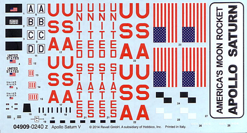
What I can't find is what they used for the lettering. I cant find what typeset 'USA' is written in.-
3
-


 ). As a mechanical engineer I do have a good idea how things should be built strong and most of all very stiff.


Kutter binoculars 120/f31
in DIY Astronomer
Posted
Started drawing a smaller version of what I called, a very, very long time ago, my 'Boxmount'.
The first one I ever made in the early '80 was a very large mount. In fact way to large for it's purpose. After that first one I made it much smaller and ended up with a equatorial mount just over 6" high to be used for scopes up to 20". Sky&Telescope did published it in one of it's 1983(if I'm not mistaken) issues.
This 'Box-mount' is nothing more then, a wooden plywood box. At the west side is a large and very strong hinge. Alongside that hinge the box is sawn in two parts. So that box can be opened end closed again because of that hinge. At the opposite side is a threaded rod. That rod is there to slowly opening or closing the 'lid' of the box. On top of the box stands a telescope, any scope. Needles to say the hinge is in fact the polar axis. In my case that hinge is mounted at 51°. Rotating the threaded rod opens and closes the box and moving the telescope with it. That's all there is to. My first version I made was 20"x20"x20"(about).
In the years I've built several of these Box-mounts, and made them always less high of course.
I was planning to build a equatorial platform, but decided now to make me another Box-Mount.
In the drawing the threaded rod is not installed yet. But there are, as I always do, a few planes to guide the upper part of that mount over these planes. These planes are absolutely necessary to stabilize the scope during action. Without these planes this mount will not function at all..!
Anyway, this is how my newest Box-Mount will looks like. It doesn’t look like a box anymore, still I call it Box-Mount.
First drawing : looking east.
Height of this mount 170mm.
Looking east
In this case I did not use a hinge but a 12mm thick axis(at 51°) running through printed parts(centre).
Looking north

Neutral position
Looking south.

mount is almost completely closed and ready to start tracking
Tracking is done by pushing the box to it's open position.
Still looking south

Box is opened almost completely so the scope has reached the end here
In this drawing the Box-Mount is completely opened to have good look 'under the 'hood'.
it's actually very simple.
With this mount I can track up to 2 hours and more. But I will not do that because that will result in tracking errors due to the straight threaded rod. I could install a curved threaded rod but I'm not planning to because this mount and telescope is for visual observing only.
The small white parts are all Teflon, this is to have a smooth ride during action.

I hope it's clear...