


John78
-
Posts
589 -
Joined
-
Last visited
Content Type
Profiles
Forums
Gallery
Events
Blogs
Posts posted by John78
-
-
So I have to disagree on the cheap Chinese printers, I've just retired mine (literally this weekend) after a few years of valiant service - it looked like utter trash in the end, it only ever required some inserts on the top of the Z threaded bars to stop them being sloppy, 1 new hotend, a new heated bed and an inductive probe. It printed like a champ, it was one of these...
The new hotend for it I moved to bowden (keeping the existing extruder motor) just to reduce the moving mass.
Now before you cry mine was a one off my brother has the next spec up with lead screws for Z and a inductive probe etc... An Anet A8, and that too prints like a champ with no fettling or upgrades at all.
So as long as you take care in assembly ensuring things are square and tight and you fix it down to something flat and print slowly it will work fine.
In terms of comparing 3D printing quality, at work we have 2 commercial statasys printers engaged full time and I use as part of my day job - they print nicer materials (ABS, polycarbonate, peek etc...), but the quality isn't much better than my home printer the caveats are printing without support material and print speed - the commercial printers soluble support material is a really neat trick and it prints 4-5x faster than I can at home.
It got retired because its worn out from use - and its last task was printing a set of tech2c hypercube parts which I finished assembling this weekend, just need to wire it up.
-
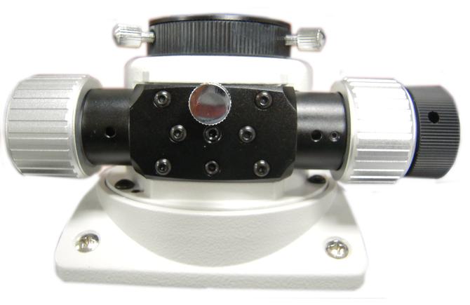
Since there seems to be some interest in tube rings - here is my version 2.0 which I've been using for a while - updated to make it user friendly and more parametric, it also closes radially round your scope - the original version is a pig to clamp up.

Hopefully the parameters should be self explanatory and where possible each sketch only contains 1 dimension to be adjusted by the astronomer!
Scope OD - change this dimesion to alter the ID of the ring
Ring Thickness - change this to make a thicker or thinner ring - I'd suggest 10mm smallest diameter < 7mm will break the model
Clamping screw diameter - the size of the axial clamping screw - currently M5 clearance
Closure and foot shouldn't need any adjustment
Clamp extrude sketches - final, no user settable parameters
Foot extrude sketch - final, no user settable parameters
Thickness of tube rings - this controls the overall thickness - I'd suggest 12mm smallest thickness
Thickness of pivot - this needs to be (0.5 * thickness) - 0.5mm
Thickness of foot ring - will auto calculate to the same as the other thickness
Thickness of foot pivot- this needs to be (0.5 * thickness) - 0.5mm
Fixing screw hole - this is currently M6, what you want to screw it down to the dovetail with
I print with 4 bottom layers, 4 top layers, 4 perimeters and 50% infill and its strong enough and the dovetail clamp is easily threaded with a tap to screw it down.
Let me know how you get on if you print it out!!
-
 4
4
-
-
2 minutes ago, jase1973 said:
Hi John, Ive taken a look as I'm intersted in some rings too. I can't see a way to download as stl.
any suggestions?
Sign up then in, then copy the workspace using the button at the top, the right click on the part and say export...

Then choose these options and click export, STL file of the part will download.

-
Well, an Anet A8 with lead screw Z axis and auto bed levelling will be perfectly fine, the kit I bought took a bit of fettling to print PLA properly and its beginning to really struggle now with using PETG - that said it is still in service today with thousands of hours of use.
Did need a new heated bed and a new hot end during its life so far though.
-
 1
1
-
-
Its free for hobbyists - the only catch is what you design is viewable by the public domain, just name your files with random strings of numbers and letters and no-one can ever find it.
It's certainly as good as solidworks 2007 and its cloud based so works on any device or OS.
-
On 24/06/2018 at 07:35, Demonperformer said:
Nice going. I keep thinking about buying one of these beasts. Currently trying to learn sketchup - no point spending out on a printer before I can produce the templates for what I need!
Dont even bother with sketchup, its a pretty picture tool not an engineering tool. Learn onshape, it will be much faster and more satisfying.
-
1
-
-
On 23/06/2018 at 23:13, mackem54 said:
its a longshot but john 78 you wouldnt happen to still have the stl file so i could print these rings im desperate cant find a print file anywhere on the net,
cheers
What size ID do you need?
The rings to that design are in part studio 2, Its probably not too robust to dimension changes - need to make a parametric model of it really.
-
On 3/26/2018 at 14:13, dyfiastro said:
Thanks for the reply.
Yes this is what I have been finding as well and indeed the issue I have been having.
I traditionally always use a Bahtinov mask but was trying to get the autofocus setup for a complete remote operation.
I am at this stage not sure if the culprit is APT or the focuser. When ever I attempt to use autofocus the focus always ends up being slightly off.
The only other option at present is to use the assisted focusing section and do it by manually. I would like it setup so that it can just refocus on the fly without any interaction.
So I've been lead to believe the HFR technique used by SGP and Ekos is very good at getting the best focus - given that SGP is paid and Ekos is "free", I've gone the Kstars/INDI/Ekos route and I've got it all up and running on a RaspberryPi and been very very impressed, its really a 1 stop astrophotography shop, but its been cloudmageddon here for about a month - so no field testing yet - I did have a brief chance to test it indoors though an open window last night and can confirm it appears to work and autofocus to the best point of focus with no fuss.
The software monitors the incoming images so if the focus is drifiting it can be setup to stop and retrigger focusing, you can also schedule focusing whenever you like, time, temp, filter changes etc...
The only issuette I had is as far as I could see this focuser software doesn't work with Ekos so I had to re-flash my Arduino with a moonlite cloning sketch instead which is available on the indi forum.
-
On 3/21/2018 at 23:11, dyfiastro said:
Hi
I have been using this focuser setup with fantastic results for sometime now.
One small thing I have never seemed to be able to get working however is for this to play nice with APT's autofocus
Has anyone used this setup with APT and managed to get the autofocus part working?
Any help or information would be great.What part isn't working for you? I had it "working" in APT with a 1000D Canon, in that APT was taking pictures and automatically adjusting the focuser - but what it decided was best focus wasn't great. The Bahtinov tool I found to be very good and you can press the buttons to move the focuser manually, but means you need to go to the mount to put the mask on/off.
-
1. no, it wont even move the focuser alone - even with 12v
2. its a reasonable option
On 12/03/2018 at 17:00, RolandKol said:1) Is this 28BYJ-48 5-volt motor powerful enough for 130PDS focuser with Canon 1300D camera (around 650g in total) in it? (I strongly doubt it will be enough)
2) In case I will succeed with a remote focuser project and will decide to move on to autofocuser, - will UNO R3 Arduino Rev3 board be the right board to interact with ASCOM driver? if not, which should I go for?
-
1
-
-
I'm pretty sure I used one of these...
https://www.firstlightoptics.com/adapters/flo-80mm-125-focus-extension-tube.html
So be able to get the DSLR in focus, the issue is, being 1.25" it vignette's quite badly on an APS-C camera.
-
25 minutes ago, tony8690 said:
You all have some amazing pictures here!
Would you say there is much difference between the 130PDS and the 150PDS mounted on an EQ5??
Thanks,
T
A 130PDS is much more reasonable on a EQ5 with respect to payload when you've added all the cameras etc... - its diddy.
-
1
-
-
I've hacked into a Canon EFS lens using this guide... https://pickandplace.wordpress.com/2011/10/05/canon-ef-s-protocol-and-electronic-follow-focus/
One of the comments in that blog has arduino code - sure enough I can control the focus and aperture of my 18-55mm kit lens after I got the code compiling.
So my next logical step, would be to modify your code - it looks like if I just un-define the stepper motor pins and then have the function anticlockwise() and clockwise() call focusRing(1) and focusRing(-1) it looks like it will work, maybe
")
And voila - it does...
So now I should be able to try the 18-55 kit lens on ZWO camera and actually be able to get it in focus!!
It should now obviously work with any Canon EFS lens as the protocols are all the same.
-
2
-
-
So just swap the nano for a mega and load AstroEQ on it then you have a full goto EQMod setup once you've built a Dec axis...
https://www.astroeq.co.uk/tutorials.php?link=/doku/doku.php?id=buildown
-
I'd be absolutely flabbergasted if what's inside that Pegasus focuser isn't heavily based on ascom focuser project I linked with a L293D or fet equivalent driver and a few code tweaks to change the name of the device etc... and then laid out onto a real pcb.
-
Word of caution with that project - you need 328 Nano's not the cheap 168's as it compiles way too big to fit on a 168...
-
9 minutes ago, SkyBound said:
the encoder control knob on the controller is superb and it moves the focuser as if you are turning the actual focuser, and by pushing it down it alters to a 10:1 speed, just like using the fine focus....really is a superb design, and not seen anything like it with the arduino projects......but at a higher cost I know...
")
This does that...
https://sourceforge.net/projects/arduinoascomfocuserpro2diy/
You can either use 4 buttons coarse and fine back and fro, or a potentiometer and a switch to swap between the focus speeds.
-
13 minutes ago, Dr_Ju_ju said:
As stated elsewhere the most expensive part is the stepper, I use these http://www.ebay.co.uk/itm/27-1-Planetary-Gearbox-Nema-17-Stepper-Motor-1-68A-DIY-CNC-Robot-3D-Printer-/121683241474?hash=item1c54e2ea02, for approx £35, together with boxes\components\mounting parts etc. the complete package can be done for £50-£60.....
I've seen that motor reported as a good candidate for a focuser in the other sourcforge focuser project, the problem I see it as is the torque of that thing is astronomic (3Nm continuous rated), you've only got to get it wrong once at that's the end of your focuser, it'll smash it to bits, that and it weighs like 500grams. Its just massive massive overkill.
If you've got a light image train you could get away with over powering a 28BYJ-48, or use a 4 or 5:1 reduction with a toothed belt straight to a nema 17 stepper, a nema 14 with a gearbox would be a better motor.
-
2
-
-
My focuser cost me :-
£3.39 arduino nano
£2.00 DRV8825
I already have stepper motors for free and veroboard etc... in my project box, so you can create one for easily under a tenner.
-
So I think this is already effectively supported with @tekkydave 's project, if you use a L293D driver it will drive your DC's for now and can drive the steppers in the future, it's not a great device for driving a stepper so you'd probably switch to a DRV8825 pretty quickly - but fundamentally it will work.
You might need to change the code to adapt it for DC driving (i.e. changing the pulse length rather than sending multiple pulses such your motor's move) other than that I suspect you will then have a ASCOM compliant DC focuser.
-
1 hour ago, Stub Mandrel said:
Put in freezer, then briefly warm the outer ring in your hand before quickly trying to separate them.
That and put on your marigolds, you'll get anything undone wearing marigolds.
-
2
-
-
28 minutes ago, Stub Mandrel said:
I have a home-made laser collimator - the key to success is collimating the collimator, luckily I have a pair of large, matched v-blocks that i can rest the collimator in and rotate it and adjust until the spot rotates but doesn't move.
I've got a Chinese one, my goodness that was frustrating to set up, 3 hours in it was still making a 2 foot circle on the wall 5m away so I completely disassembled it replaced the gromit and all grub screws with real ones not Chinese cheese ones and got it adjusted in a few minutes.
-
3 minutes ago, carastro said:
Well I have been trying to collimate it, it seems a fair bit off. Not had a lot of experience with collimating despite having two Newtonian's before as all I ever had to adjust was the primary, but this time the 2ndry looks like it needs adjusting.
a) The central screw on the spider is locked tight, I am not quite sure if I need to adjust this but it's not budging and I am nervous of using force.
b ) There was no hex key included with the scope so I don't have a hex key to adjust the tilt as currently I can't see all 3 primary clips in the secondary, I don't think just adjusting the primary mirror only is going to cut it.
I have mislaid my own hex keys (assuming I have one the right size, and husband's all are attached to a ring with a 90 degree bend at the usable end.
I have been through all the packing several times to see if I have missed a hex key, yet I have a spanner and a screwdriver supplied.
Stuck now

Carole
You can pull them off the ring to use the straight end.
My 130P was miles out when it arrived, then I chopped the end off the tube and had to recolimate it again, the spider vanes are probably twisted also mine were on arrival, you need a MASSIVE handled screwdriver to crack that Philips screw also.
-
So I can't get my 130P into balance due to it being from an AltAz goto mount originally (£30 from astroboot) the tiny dovetail puts the tube in the wrong place with a camera fitted and the wrong rotation also.
I acquired a £147 3D printer kit from eBay a week or so ago, and honestly it's required far less fettling than I thought it would to get acceptable prints so within a day or so of it arriving it's producing prints with correct dimensions.
So this weekend I printed out some tube rings, designed on onshape - which is a proper CAD package for free and cloud based can't recommend it enough - it's like solidworks. It's even usable on your tablet.


I've also printed a baht mask although it was a right pig to get off the heated bed...
Anyway happy days, next project will be a 3D printed tracker for SLR and lens I think so I can have a portable grab and go setup for the unexpected imaging windows.
-
13
-


3D Printers
in DIY Astronomer
Posted
Well the motors are £6 each, the electronics is £11, the hot-ends are £5 and the heat-bed £6 - all from UK ebay suppliers, so they can only be making £5-10 profit.
I normally agree with your mantra - and I also like buy cheap buy twice, or quality remains long after price is forgotten, but in this case, in my experience - it works, motors are motors and the electronics all run the same software with the same capabilities (until you start moving up to trinamic drivers).
My strong piece of advice would be don't skimp on the filaments.
What I would plan to do if I was starting from scratch without access to printer and a machine shop, would be buy the cheap printer, print the dbot parts and buy the dbot kit from ooznest - then your in for ~£275 and will have an incredibly capable machine.