


vlaiv
-
Posts
13,106 -
Joined
-
Last visited
-
Days Won
12
Content Type
Profiles
Forums
Gallery
Events
Blogs
Posts posted by vlaiv
-
-
It looks like first batch is seriously flawed (hence recall).
TS in Germany has them listed now - but not yet available - expected to be in stock within 3 days - I wonder if those will be "proper" ones - or ones that are recalled.
-
Found it - here is filter:
https://www.cyclopsoptics.com/astronomy-filters/stc-astro-duo-narrowband-filter-48mm-2/
and here is the thread about it:
-
 1
1
-
-
Someone recently reviewed such "double" NB filter - I can't remember what's the name of filter nor manufacturer - but you can maybe find it somewhere in SGL via search.
If you want broadband general purpose LPS filter - then IDAS P2 is very good choice - I have it and use it on both OSC and Mono cameras (for luminance). I'm pleased with it so far.
-
It looks like a very good filter if it matches response curve in the image - but it is certainly not LPS filter and Galaxy improvement of 95% is just ridiculous.
This is very good UHC filter by the looks of the spectral response curve. It should pass following wavelengths:
486.1um - H beta
495.9um & 500.7um - OIII
And it has peak that is probably passing:
656.28um - H alpha
maybe even
671.7nm und 673.0nm - which are SII, but that peak looks rather narrow to be ~20um wide (on second image it looks like it has FWHM of about 10um in that second peak, so maybe not SII lines).
If you want "comparison curve" - take a look at other UHC filters and their curves. Such filters are best suited for imaging emission nebulae (or observing them).
BTW, one can't judge filter only by it's transmission curve - surface accuracy, anti reflective properties and durability all play a part in overall usefulness of filter.
-
43 minutes ago, alcol620 said:
Last post awhile ago, but here goes.
Interested in your choice of lens to fit to the ASI1600. I have used the stock canon lens but these give me really bad stars away from the centre of the image, even when stopping down the lens. Presumably with the Sigma lens this works out fine?
Any other views on the best Canon fitting lens to provide the best match for the ASI1600?
thanks
Don't know about the best, but from what I've heard Samyang 135mm F/2 is held in high regard for wide field with ASI1600 (and other sensors).
-
I can't remember exactly, but you list does look right - there are three distinct types: small ones that go on worm shaft, large ones that go on main shafts (RA and DEC) and conical one that goes on dec where CW shaft extends.
I just took mine with me, went to local shop - showed them to the guy and said "I want the best ones like these" - he gave me bunch of SKFs

Further "mods" that you could consider would be better tripod (if not pier mounted) and saddle plate.
There is one "trick" you might want to try also - but involves just settings. DEC axis can have different amounts of backlash depending where on "circle" you are checking - and if you remove backlash where there is plenty - you will get stiff motion on opposite side. If you adjust where is little backlash you might still get some backlash on other side. If this happens - you can actually determine range of DEC motion that you are likely to use with your mount - you are likely to go below equator on south side, but you are not likely to hit anything close to horizon on north side, so it is likely that DEC won't do full 360 rotation in use (it might do even less if part of sky is not accessible from your location). Place problematic part of DEC where it will not be used by turning it either by hand (worm wheel when mount motor cover is off) or in EQMod - by slewing to that position and then resetting motor position to home (not parking to home but resetting to home - if you have done PEC, make sure you don't do slew in RA - keep it as is - in home position). Return scope to home by undoing clutches.
-
1
-
 1
1
-
-
1 hour ago, DarkNorth said:
As I mentioned above AP is something for later on, I don't have the budget for a camera in the short term, and with health considerations would be something I'd hold back atm, just being able to view things beyond the naked eye would be a good starting point.
Size is a factor to a point, as due to spinal fractures/osteoporosis I will have a limit on what I can carry myself - this may improve with time.
As far as Go to Mount is concerned it would be something I'd like to get. EQ mounts were mentioned for best at tracking as you don't need to manually follow, but I guess a go to does pretty much the same thing. SO maybe thats something for more advanced interest in astrology later.
Narrowing down the scope to fit the criteria (and mount etc ) would be the main thing now. I've looked at the ones listed above. And my budget could be increased a little to accommodate a bit better scope if I felt it was the right one to get.
The one mentioned 200p with goto Looks a possible. How do you know what eye pieces fit or is it a simple case of the right brand/right size?
Thanks.If lifting heavy things is a concern, then think again about 8" dob. It's not the largest scope out there, but it's bulky. Basic version without goto is 26Kg - divisible in two parts. About 11Kg OTA (Optical tube assembly - or scope main tube) and about 15Kg base. OTA is somewhat bulky but easily carried by one person. Base is bulkier and you can carry it via handle - it feels like lugging around heavy bulky travel suitcase.
Goto version is a bit heavier - due to motors on the base.
-
1
-
-
Hi and welcome to SGL.
If you want a scope that will do almost all things well - planets and Moon, galaxies, star clusters, double stars, nebulae, etc ... and you don't have special requirements for travel or such, this is simply the best option:
https://www.firstlightoptics.com/dobsonians/skywatcher-skyliner-200p-dobsonian.html
It is a bit larger scope (maybe look up some videos on youtube to get idea of its size), and while it is excellent "starter" scope - it is also scope that many people consider "for life". It comes with all basic accessories that you will need to start observing (eyepieces and such) and considering your budget you will have enough for additional books on astronomy and any eyepieces, filters, barlows etc that you might like to add at some point.
You did mention that you would like a goto version (above is manual) - there is such scope in "goto" variant as well, but of course it is more expensive (and above your budget I'm afraid, so if goto is something that is very important, there are other options):
https://www.firstlightoptics.com/dobsonians/skywatcher-skyliner-200p-flextube-goto.html
Something else to consider is that this scope is not suited for astrophotography and in general astrophotograpy requires dedicated equipment and is quite a bit involved and expensive. One can certainly do astrophotography on a budget and even get decent results, but it usually means not using telescope and just using camera and lens on a simple (yet good) mount. Once you start thinking about telescopes and astro photography, then you need to start thinking in thousands for budget.
-
3
-
-
Some math is in order to answer that question.
Don't know if I'm going to quote specs right, but I'll do the math so you can "fill" in the right values and redo calculations if necessary.
You'll be using 50mm focal length with sensor that has 5.7um pixels and 3888 of them in width.
First we need to establish working resolution in terms of arc seconds per pixel - and we use following formula for that:
resolution = 206.3 * pixel size / focal length, and when we swap in the values, we get ~23.5"/pixel
Next thing that we need to know is sidereal rate, and that is ~15"/s, this means that each 1 second, sky will move 15".
If you align your camera so that width is in direction of RA, we can then translate sky motion in number of pixels. In 300s at a rate of 15"/s, sky will move 4500". Since we have ~23.5"/pixel resolution we can now calculate number of pixels that sky will move in 300s - result is ~191 pixels.
Since your camera is 3888 pixels we can use this to get percent of frame displacement compared to width of frame. This turns out to be a bit less than 5% (100% * 191/3888).
This is very small movement between first and last frame and stacking software should easily pick up on this. You will not loose much of image due to stacking crop either - only about 5%.
-
1
-
-
1 hour ago, haitch said:
If you think about it... What is a correct upright image in astgronomy???
I used to have a WO prism diagonal but it wasn't as contrasty and anything bright gave a strong diffraction spike through it.
Although I know what you mean by image orientation, and the quicker one learns that orientation is not important - the better (what is important is relative positions of objects), there is actually a good reference frame to define correct upright image.
It's after all relative to observer - if image in telescope matches that of particular observer without using any instrument - "plain eye sight", then we can say that it is correct upright image for that observer.
That kind of reminds me of the famous fallacy - "Why does mirror invert only left to right and not upside/down?" (it does not do only left/right - it is only due to "standard" position that we think of mirror being placed that it inverts only left/right - hold the mirror in your lap for example and look at it from above - image of objects in front of you will be flipped vertically).
-
3 minutes ago, Alan64 said:
A catadioptric is any telescope where refraction and reflection are combined; lenses and mirrors
Just add "to form the image" at the end of that sentence
Refractor is well capable of forming the image without use of diagonal (either mirror or prism).
If you want to be more specific, then there is divide in catadioptric telescopes in true catadioptrics and hybrid catadioptrics, have a look here:
https://www.telescope-optics.net/catadioptric.htm
"Strictly talking, catadioptric telescope is designed as a synergy of reflective and refractive elements, requiring both for its functioning. Such design is sometimes called true catadioptric. That separates it from hybrid catadioptric, usually a mirror telescope using refractive field-corrector, which can function without its refractive component."
But in all cases both reflective and refractive elements need to alter waveform and converge/diverge light beam to be considered integral part of telescope design.
Although Newtonian is considered two mirror system (it's got two mirrors, right?) - it is not really - it is single mirror system, and you can use such telescope without secondary mirror (for photographic purposes for example, much harder for visual as one's head would be in the way).
-
1
-
-
25 minutes ago, Alan64 said:
People use diagonals regardless if they are good or bad because it's far more ergonomic. Straight-through observing is a lost practice for the vast majority, save for the Japanese(at last count).
The secondary-mirror of a Newtonian is that telescope's "diagonal". Have a look at this "refractor"...
That is a catadioptric.
In so far as a diagonal not degrading an image, think again. The more you add to the light-path, the greater the chance for degradations; light-scattering in the case of a mirrored diagonal. Then, there's the miscollimation of either a mirror or prism with which to contend.
When one does place a diagonal into a refractor, you still can't use the telescope until you add an eyepiece, therefore the diagonal, when integrated, becomes one with the refractor, a component of the telescope's light path, and just as the secondary-mirror of a Newtonian; therefore, again, a catadioptric when using a mirrored diagonal. I suppose, rather, that you might hold that a Newtonian becomes a catadioptric when an eyepiece is inserted; most definitely not a refractor by any stretch of the imagination; however your point is moot, as eyepieces are not an integral part of a telescope's light-path, rather the receivers of the light-path instead. Observe what happens when the tip of the light-cone of an objective nears an eyepiece...
Note where the tip of the light-cone ends, and just as it exits the body of the diagonal.
Eyepieces are, again, merely receivers, and therefore cannot transform any telescope into another.
This is my 80mm f/6 achromat, but with a 2" mirrored diagonal. Configured so, it is in a catadioptric mode of operation...

If I take the mirrored diagonal out, and put a prism diagonal in its place, the telescope then reverts back to being a refractor; closer in any event, as some regard the "total internal reflection" of a prism diagonal as just that, a reflection. However, there is no light-scattering, aluminised coating involved. In a straight-through configuration, without a diagonal at all, the refractor is at its very best, in form, function, and performance.
Incidentally, in the case of a barlow, if inserted before the diagonal it becomes a part of the telescope's light-path. If the barlow is inserted after the diagonal, it becomes a part of the receiver, the eyepiece.
2" mirrored diagonals are more popular not because they're so very wonderful, but simply because they're cheaper to make, and purchase. I do not look upon mirrors as a cure-all, and as so very many others do.
If you go by the definition: Catadioptric telescope is one combining reflective and refractive elements to form the image at focal plane of the telescope - then you could say that refractor + diagonal is catadioptric telescope.
Then there is different definition: Catadioptric telescope is one using both reflective and refractive elements to shape light into forming an image at focal plane - then flat diagonal is nothing more but device to position focal plane without altering the shape of light beam. It is not altering the waveform in any way (not deliberately / by design at least).
Most people when using term Catadioptric system - thinks second definition, so refractor + diagonal is not considered to be catadioptric telescope.
-
1
-
-
It has more to do with beam angle than with objective, so fast scopes + prism = some color, regardless of type of objective (ed, apo, ....).
If you want correct image orientation over other things, then erecting prism is the way to go.
These tend to be expensive in high quality/astronomical variants. At low powers I don't think that color nor lesser quality diagonal will be much of a problem though.
-
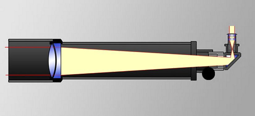
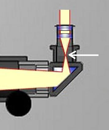
Quick update - I decided to ditch whole laser thing and go with relay lens system.
I've got 4" F/10 achromat that will serve as "beam" and 80mm F/6 apo that will be receiver - this way I'll get image reduction. This is a bit larger setup (will hold a scope on the mount), but one can use finder as a light source and something simple as short focal length lens on camera side to the same effect.
System will be made out of simple light source (small torch) and aluminum foil pinhole - just need to fashion mounting rig for that at focal point of larger scope (duct tape to the rescue!) and do preliminary tests (two az mounts, well AZ4 and photo tripod or table top will do to test out relay system and see what kind of image I get on sensor).
-
With increasing interest for astro photography, question is often raised about suitable equipment under restricted budget.
Many people can't afford what would most consider adequate start of mount for serious AP (HEQ5 class), and there are some cheaper alternatives on the market but I think we lack proper understanding of performance of such mounts. Even higher priced mounts rarely come with graphs depicting mount tracking performance (such as obtained by high resolution encoders coupled to RA shaft).
I wondered if there is a way to qualify generic mount tracking performance, and by generic - I mean, out of the box, unloaded, with no external influences - like wind, seeing and all other things that hamper mount performance additionally. A way to measure p2p periodic error and also smoothness of tracking.
This would be considered as "baseline" mount performance, and real time usage would probably yield performance worse than that. While parameter like - "mount will perform better than ... " could be viewed as generally more useful one - I think knowing baseline is also useful - and the way of measuring it is nice "indoors" project for cloudy nights
Idea is rather simple, but it looks like it will take some creative thinking to get it to usable level.
Initially I thought of following:
Take a laser pointer (collimated light beam) and mount it on top of dovetail clamp in some way so it is secure - pointing to the side, so that beam is close to level. Take telescope and camera (equipment that most imagers have so they can readily test their mount) and place telescope with camera attached so that laser beam initially coincides with optical axis (or close enough). Since laser light is close to collimated (probably diverging very slowly) - it will act as a distant point source when focused and project a spot on sensor.
Tracking of scope is then engaged and sequence of captures is taken. Data is later analyzed and centroid of spot is calculated for each frame. If light is bright, even very short exposures in quick succession can be recorded - providing very detailed graph. Spot should move slowly across sensor - one can even calculate the rate of motion for fully collimated beam.
Sidereal rate is 15"/s, and from telescope focal length and pixel size - we can get sampling resolution. Let's take common setup - something like APS-C sized chip and short frac. Such setup often has 2"/pixel, so in one second spot should move about 7.5 pixels. If sensor has for example order of 3000-4000px across - that will let us record about 500 seconds of tracking. With use of focal reduction, most mounts can be sampled over whole worm period.
I started researching into lasers - but it looks like that might not be viable option, I'm afraid that concentrated laser beam might damage the chip! Full power of laser (even very low power one, like 5mw) will be concentrated over few pixels - extremely short exposure will be needed to avoid saturation, and I'm really worried about damage to sensor.
Does anyone have idea if laser would be feasible? Maybe strong ND filter, or even better - solar filter film - really small piece would be enough to filter out laser light to acceptable levels?
Other ideas would be - artificial star - but then there is issue of close focus - most telescopes can't focus close enough to do it indoors?
Another option would be artificial star with collimation lens? Or simple variant - eyepiece. One would place artificial star at field stop of eyepiece (involves unscrewing 1.25" nose piece) and testing against the wall - projected image should stay roughly of the same diameter - maybe diverging ever so slightly (less divergence - further out object appears to be). My worry is that in case of collimated artificial star (or simple tiny whole in some sort of screen) - there will be very large image on the sensor - whole setup will act as relay lens system with magnification (image - short fl - long fl - projection). Maybe that won't matter as we are interested in measuring center of the image as it moves - it does not matter if it's a single spot or a circle - as long as measure of position can be taken (like center of mass).
Laser sounds more interesting because filter can be employed on sensor star (laser at 532nm and Baader solar continuum for example) to boost SNR if measurement is not done in absolute dark. Question is only - is it safe to use, and if no - can we make it safe?
What are your thoughts at all of this?
-
I just discovered these:


I've been thinking about doing something similar with planetary/guider cams - it looks like there is software to generate these maps.
Simple photo tripod with 1/4 thread can be used to mount most planetary cams. Simple CS wide lens can be used - like those used to capture meteors. This gives much better info on sky lp - especially for imagers as it provides direction information - useful for selecting targets. One can even do sequence of images over the course of the night to do idea of changing levels of light pollution (lights going on and off).
-
2 minutes ago, Demonperformer said:
To where should it be submitted?
There are couple of places (you can find them in links section on SQM-L/Unihedron website - check "Light pollution maps / databases" section).
You can also submit your reading to lightpollutionmap.info

You can also view submitted readings with additional info by selecting appropriate layer (color dots used as markers for location - click on one to get info on readings):

-
2
-
1
-
-
25 minutes ago, Ags said:
My skies are Bortle 7 according to the site, which would mean M31 would be possible naked eye, which hasn't been my experience.
Regardless of what the map says, there is a lot of variation. Some nights feel like Bortle 6 and a lot feel like Bortle 8.
Same here, and it says M31 difficult with averted vision and MW invisible.
I managed to see M31 on few occasions with averted vision (maybe twice or three times at the most), but I was also able to see hints of MW at zenith, probably more times than M31. Only once have I managed to see M31 dust lane with 8" scope from my location.
These things vary with transparency, so LP is not the only factor. Aerosol optical depth extincts light quite a bit, and for my location I get variations from below 0.1 to above 0.5 - when southern wind blows it can lift Sahara sands and carry them all the way across Mediterranean Sea. More than once we had "muddy" rain because of this in past few years.
This is why it is useful to check out aerosol optical depth forecast (finally managed to find the page, they kept changing it lately):
-
1
-
-
3 hours ago, scarp15 said:
That online mapping resource is misleading, inaccurate and delusional and certainly should not be used for quoting as a reference in any observers reports. If I was to quote from this map based upon locations I go observing within then I would be implying SQM 21.88. Whilst I gain 21+ mag skies, this particular reading is quite simply - at least so far - untrue. A Unihedron SQM-L (check FLO) is a highly useful tool for measuring / assessing an average and monitoring sky brightness over a given period during your observing session. Anything else is quite simply for the birds, at least in my opinion.
You know how the saying goes: "one man's trash is another man's treasure"
I found that website to be extremely useful tool once you understand it's limitation and application. Readings with SQM/SQM-L will certainly vary across nights and will be different to map as map probably represents annual average value, or at least average value of recording times (which might or may not be uniformly dispersed throughout the year). VIIRS data is actual recording taken via satellite of ground sources total illumination. Atlas data represents numerical approximation of sky brightness made by integrating ground sources illumination and atmospheric scatter - I think it is very clever that they managed to get it to such level of precision.
One needs to distinguish sky brightness to other things that impact visual astronomy. Transparency, both local and high altitude can have significant impact even in very dark skies - this can make one observing site preferential to another one. SQM readings on particular night might vary significantly to this map. Amount of water vapor in the atmosphere can contribute to light scatter quite a bit, light sources are very dynamic, lights get turned on and off, it even depends on traffic density and road conditions if you have significant road network near by. Dry road and wet road have different reflection properties. Snow increases light pollution quite a bit. So many things impact this that it is quite a miracle that such map works and works so well - within mag 0.5 in most cases - that is up to 63% of base value.
1 hour ago, wookie1965 said:what do the numbers mean?
Brightness and Artificial brightness are probably ground luminosity recorded by satellite. First being just natural sky glow reflected of the atmosphere and ground, and second artificial lights on ground - what we think of when we say light pollution.
SQM is magnitude per arc second squared and can be thought of as: if every arc second x arc second (square with sides 1 arc second) contained a star with apparent magnitude of XX without any other light sources in the sky it would be as bright as sky is now. Just for comparison, Vega is 0 magnitude star, and Jupiter has about 1600 arc seconds squared of "angular surface" when largest. Every 5 magnitudes is x100 less light, so mag20 star is 100,000,000 times fainter than Vega (hope I got number of zeros correct
). It should consist from natural sky brightness (zodiac light, milky way, stars ...) + atmospheric scatter of artificial light from the ground. When there is no artificial part, natural brightness is at 22mag.
This number is more meaningful to imagers than observers because it can be used in SNR calculations. It is also useful to guess visibility of some faint objects if you compare that to surface brightness of those objects - this is what Contrast Index in Stellarium for example represents:

Ratio of brightness of target to brightness of background sky. Surface brightness in Stellarium is given in magnitudes per arc minute squared, and for conversion one needs to
subtractadd 8.89 to get magnitudes per arc second squared. Do be careful with surface brightness in stellarium - it is average value and real value can vary quite a bit - think galaxy core vs outer parts - core is way brighter than outer parts.Ratio from above info represents how many times that particular sky is brighter than natural unpolluted sky in zenith.
Altitude and coordinates are self explanatory, me thinks.
-
5
-
-
3 minutes ago, Demonperformer said:
That is always a possibility as I have never had anything to which to compare it. Possibly the proximity of my two nearest streetlights are having a disproportionate influence. When I put my Ne3 filter in front of the lens (I did this to measure the sky brightness for each of my filters to enable me to calculate appropriate sub-lengths) it goes way down to 23.0. So if my meter is reading 1.5 mag too bright, then that would mean I would be getting a sky brightness of 24.5 with that filter. I think that might be a little too hopeful!
Not really if you think about how magnitudes are calculated - it is ratio of brightness to a reference point (0 magnitude). Just because natural sky has brightness of mag22 - that does not mean narrow band can't have much lower brightness.
Simple example would be as follows: let's take 400-700 spectrum and we approximate uniform brightness over that spectrum. Full spectrum under consideration contains 300nm. Now take 3nm narrow band filter. It will collect x100 less light. x100 is 5 magnitudes of brightness down. Such filter would measure mag27 if our source is mag22.
Now take into account that light spread is not uniform and that some wavelengths carry more brightness than others - you can easily see that this difference can be over 5 mags for narrow band filter.
-
1
-
-
1 minute ago, Demonperformer said:
Thanks. vlaiv.
As above, the actual reading varies from about 17.4 to 17.6 ... I just wish I could get 19.3!

That is quite a bit of difference!
Most that I've heard is like half a magnitude of difference between SQM reading and Light Pollution Info. Maybe your SQM meter is not calibrated properly?
For example:
This is what light pollution info provides:

And these are set of measurements on star parties in 3 years:

Btw this shows increase in LP levels over time - first measurement is done in quarter moon but is still the best.
-
Here it is, but it is worse now than 3 years ago - a lot of development / new construction right near me.

Viirs data 2015 vs 2017:


But I hope to move to:
This year at the end of summer
. We decided to move out of the city and looking a place to build a house (and obsy at some point) - this is my favorite location so far:
 11 minutes ago, Demonperformer said:
I'm obviously being incredibly dense, because I can't see how to get the data box that everyone else seems to have found and posted (I've got all the SQM boxes ticked)!
But the entire local area is coloured pink, which according to the legend means that it is better than 18.5. But readings taken a couple of days ago (at 3am) were between 17.4 and 17.6.
Go figure.
Just click with your mouse pointer on lightpollution info map and there will be popup with said info
-
1
-
-
41 minutes ago, Whirlwind said:
I think you may be correct in that the filter has an effect but perhaps not in the way you are thinking.
I would suggest the following reason for an enhanced effect in the narrowband filters. It appears to be generally accepted that the diffraction pattern is off the microlens. However it is a lens that likely diffract different wavelengths by differing amounts. In a broadband image you have many different wavelengths that are all being diffracted by a slightly different amount. As each wavelength is diffracted slightly differently than they all overlay at the sensor in a slightly different way. As the pixels are (at a broad assumption) broadly equivalently detected then these patterns merge and form one continuous 'blob' (highly technical term). Hence you likely get a broadened star but with no pattern.
As you place narrowband filters in the imaging train you now have one specific wavelength which has one specific diffraction pattern. As there is no other wavelengths affecting the CCD you get to directly see that diffraction pattern.
In effect the broadband image is like taking thousands of individual narrowband images and then slightly altering the pattern so that when they overlay they have merged.
As such you can clearly see the effect in narrowband but not in the broadband images, but it is still there.
This should be testable by using consecutively broader filters. If you started with a 3nm Ha filter and then tested the same exposure using a 5nm, 6nm, 9nm, 12nm Ha and so forth then as you broadened the wavelength range you should see that the effect 'fades away'. It might also explain why some people don't see the effect. They are using wider narrowband filters compared to someone that easily sees it in a Chroma/Astrodon 3nm.
One could try progressively wider band pass filters, but even if we don't see pattern without filter, we would still be able to detect it - by light level around bright stars when no filter is present. One can measure background "scatter" levels further away from the star and right in vicinity of the star - they should be different in case of this effect layering on top of itself. I believe it should also be visible "by naked eye" as gradient that starts of at star then fades away further from it. This is what I pointed out as missing in no filter image above.
I do have a "model" of how interference filters and ASI1600 can produce such artifacts due to micro lenses that is dependent on both wavelength and presence of interference filter (and depend on it).
Mark (sharkmelley) stated that it is definitively due to sensor cover window as reflections produced come from source that is less then 1mm away.
I did some quick (but also maybe inaccurate due to this) measurement of reflection diameter (first order) on one of my OIII images. According to this reflection distance calculation:
http://www.wilmslowastro.com/software/formulae.htm#REFLECT
Source of reflection is about 2.6mm in my case. Only thing that I can think of producing such reflection would be camera chamber window that is AR coated and should not produce pronounced reflection because of this on its own (unless of course AR coating is not adequate).
What can happen, at least I think it can, is following: Interference filter placed close to camera chamber window (not sensor cover one) and parallel to it, can maybe create Fabry Perot filter configuration thus turning AR coated window in very effective blocking / reflection window - and this together with micro lenses then proceed to produce artifact. Light would pass forward thru filter + AR coated window because of angle and then get reflected of micro lens in all directions thus changing angle. This reflected light then encounters AR window + interference filter combo that acts as reflection filter and gets reflected back to sensor producing artifact. This is of course simplified explanation - in reality it would be multiple interference of light with itself with one component of the wave being reflected of interference filter.
-
4 minutes ago, Louis D said:
Height-wise, 6" and 8" work out to the same length because the 6" is f/8 and the 8" is f/6. 6x8=8x6=48 inches in focal length of the optical tube. The main difference is in girth and overall weight (and price, of course). If a car can fit a 6", it most probably could also fit an 8". Of course, if you're camping, there isn't much room left over for gear in a small car. If you've got a van or large SUV as many of us have in the US, they can be swallowed up with ease in the back.
Yes, I know they have about the same length (focal length at least, tube length depends on secondary size as well, and how much of tube there is after focuser - good figure, not often utilized in mass produced scopes would be x1.5 diameter), but size is quite different - base is also a bit wider and quite heavier in 8" model - around 16kg vs 26kg total (base + OTA). Not something that can easily be seen on video though


Has anyone seen the new ES 82 LER Eyepieces?
in Discussions - Eyepieces
Posted
Quite right! Expected delivery time on TS website changed to 1-3 weeks