


vlaiv
-
Posts
13,106 -
Joined
-
Last visited
-
Days Won
12
Content Type
Profiles
Forums
Gallery
Events
Blogs
Posts posted by vlaiv
-
-
33 minutes ago, Wasp said:
I have the ASI294MC Pro, you can select how much you want to go below ambient.
In that case - just set wanted temperature and take darks. When doing lights, just make sure you select the same temperature. Be careful that you can reach set temperature. I use ASI1600 and it can do about 45C delta. This means that I have trouble using -20C in summer time as ambient temperature sometimes goes above 25C at night. I use two set of darks "winter darks" - at -20C and "summer darks" which are at -15C and apply correct ones depending on lights for the night (either -20C or -15C).
If you shoot darks with camera taken of the scope - be careful of any light leak, both in visible light and IR. Some people use aluminum foil in addition to camera cap for this reason. I have a simpler method - just put plastic cap on and place camera face down on wooden desk - it works.
-
5 minutes ago, Wasp said:
I have a TEC camera and thought of doing the same. But dosent the temp have to match the light frames? How much can they differ?
Do you have a set point cooled camera? If you do - you can adjust temperature of sensor, so it will be at the same temperature when doing both darks and lights.
Yes, for proper calibration you need to have a matching temperature - not sure how much difference there is allowed to be, I guess it depends on dark current - stronger dark current requires less temperature difference.
-
 1
1
-
-
8 minutes ago, Wasp said:
Does anyone here start off doing there dark frames whilst sorting out there guiding?
Provided that you have separate guide scope - I don't see why not, you can take darks and calibrate guiding at the same time.
I use OAG so I can't do that as my guide cam depends on light from main OTA and it needs to be open for that thus preventing acquisition of darks (good thing is that I have cooled imaging camera so I take my darks during daytime off the scope).
-
1
-
-
Great animation!
At first gif did not load properly, but now it is shows fine.
-
1 hour ago, kirkster501 said:
Think: If you are imaging a nebula, say, and subsequently discover that you have star trails, the nebula will be trailing as well....... No amount of tinkering in deconvolution or sharpening is going to change that fact. Past a certain point, the sub is useless and you are defeating your purpose of creating a nice picture by trying force dodgy subs into your final composite.
I agree that no amount of deconvolution is going to change the fact that original sub is blurred all over the place

But I don't agree that proper deconvolution is not going to remove the blur, after all that is what deconvolution is - inverse operation from convolution. In mathematical terms, given original function and "blur" function when you convolve the two (blurring is convolution of two functions), you can take result and deconvolve the result with "blur" function you are going to get original function - not approximation but true original function.
There is well known relationship between operation of convolution and Fourier transforms of each original function and blur function that goes like this:
Convolution of A and B is equal to Inverse Fourier Transform of product of Fourier Transforms of A and B. In another terms - convolution in spatial domain is the same as product in frequency domain. It is therefore easy to see that you can easily inverse the operation, because there is simple inverse of product - division.
In fact basic deconvolution algorithm, known as inverse filtering is doing just that - you take both functions, do Fourier transform, divide the two and do inverse Fourier transform. This works well for noise free images that are band limited and sampled properly.
When we work with image data, there are couple of constraints to this - we work with incomplete functions - sampled functions, and there is no guarantee that either or both functions are sampled properly (band limited / Nyquist), and there is addition of noise. For that reason we can't do complete/proper deconvolution, since we lack information on both original function and blur function, but we can do a very good estimate of original function given that we have good estimate of blur function (with a bit of math magic - statistics and such).
-
14 minutes ago, mikey2000 said:
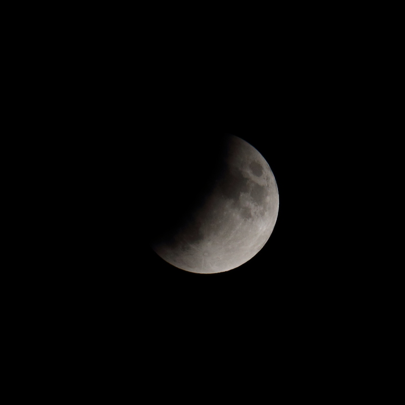
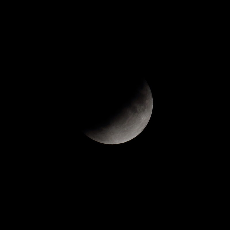
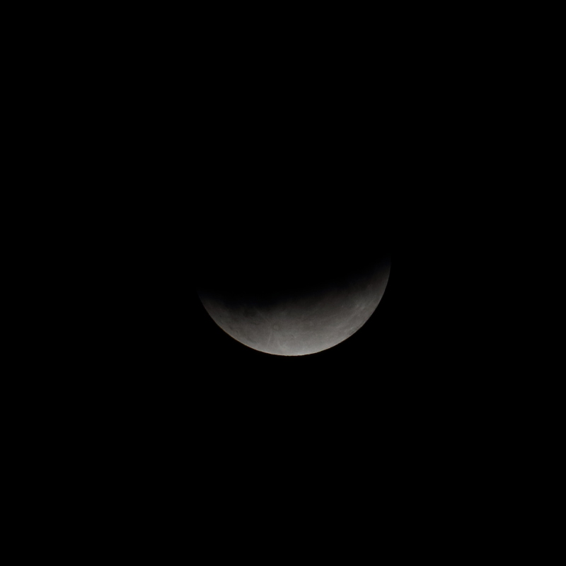
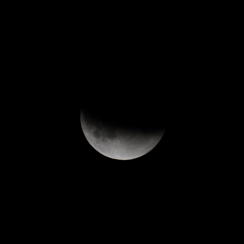
Nice shapes and detail. However, I think the DSLR white balance let you down a little too - shouldn't it be more orangey/yellow/red/sunset coloured? Here in the UK is was most definitely not the usual bright white moon colour.
I took raw images and used Canon utility to do auto white balance. Did not really try to get any particular feel out of the images. Here, Moon was like regular yellowish / white color, like you normally have in a full moon when it is well above horizon.
-
Here are couple of snaps of lunar eclipse. Nothing fancy, just plain old DSLR on tripod with simple lens.
All are single frame using EOS760d and 55mm-250mm basic lens. FL 250mm, F/8, ISO400, 1/400th.
Images are cropped and reduced to 50% of their size (too much noise and not sharp enough at 1:1)

-
15
-
-
2 hours ago, Datalord said:
Right, in PixInsight I do it by getting a PSF image from a selection of stars.
Here's what I will try :
1. Stack the good frames. Get a psf from this stack.
2. Weight everything in subframeselector.
3. Stack all the weighted subs.
4. Deconvolute on the big stack using the psf from the good stack.
Does that make sense?
I would try following provided PI offers such functionality (and I'm guessing here since I don't use PI, but going by what you said you can do - it should be doable).
1. Split frames into two groups - use frame selector or something like that and create two proper stacks by using weighted average and sigma reject and all. One stack should be with tight stars (let's call it good stack) and other containing all other frames (let's call that one poor stack).
2. Extract PSF from both good stack (good PSF) and poor stack (poor PSF). I'm guessing that actual PSFs are again image - rather small image, something like 32x32px or similar but still image that you can process as any other image?
3. Deconvolve poor PSF with good PSF. I'm guessing here that you can do RL deconvolution with arbitrary PSF (being an image - small in size like above mentioned 32x32px). Let result be known as blur kernel
4. Deconvolve poor stack with blur kernel (again same thing, hope you can do deconvolution with arbitrary image) - let result be known as deconvolved poor stack
5. Combine good stack with deconvolved poor stack using weighted average (do SNR based weights on each).
Hopefully this will produce something resembling decent result - do post it if you do it, I'm keen to see how it worked out with above approach (which is not optimal, but in theory if you can do all the steps - it should work and produce a result).
-
1 minute ago, Datalord said:
It seems to me the algorithms should be able to take FWHM and elongation into account, reduce the weight drastically in the direction of the elongation compared to the reference image and still add "something" in the area matched by the reference.
This actually is so intuitive to me that I assumed this is what happened in the winsorized algorithm?
You can try and if there are couple of distorted frames (those having distorted stars), in principle it should work. Algorithm will reject pixel values out of place, so most stars will be considered out of place (central part too dim, outer parts too bright compared to majority of frames). Background will be the same in both so it will improve noise of the background.
Problem is however number of such frames - anything more than few and you need to raise your clip threshold and that will impact other regions as well (too much rejection will lead to poor results) - in the end you will end up with worse result than including only suitable frames.
Better approach is to try to correct distortion. It can be done - deconvolution is the way to do it. It is used to reduce blur / sharpen image. In this case one is guessing blur kernel (usually Gaussian of certain sigma) - and it works well on high SNR Gaussian blurred data. In general case, problem with deconvolution is finding proper kernel (way star image was distorted) - as it is random in nature (can be due to seeing, or wind gusts, or cable snag or poor mount tracking / guiding, ....). Luckily, with this sort of images there are plenty of subs that are "decent" - and one can use those to "extract" blur kernel for any particular sub.
That involves matching stars from sub that we try to correct to reference stack (it is better to do it against the reference stack rather than single reference frame because stack has better SNR). You take each of distorted stars and deconvolve with matching star from reference frame (just take small ROI around each star for operation not whole frame) - for each of those stars you will get blur kernel, but it will be noisy because original frame that we are trying to correct is noisy, so we proceed by stacking/averaging blur kernels and we end up with something acceptable which we can use to deconvolve poor sub.
-
In ideal world you could use all frames, but that would involve following:
1. Detecting suitable frames
2. Stacking suitable frames to create reference frame
3. Figuring out blur kernel for each of non suitable frames based on star shapes and that of reference frame
4. Deconvolving non suitable frames with blur kernel / making them "suitable" (but also increasing noise content)
5. Stacking all frames weighted based on SNR of each (subs that were once non suitable were corrected and their SNR changed - hence they will have lower weight but will still contribute to final result).
Above is a "general" approach - that can be used even if you have "all suitable" frames of different FWHM. You can select target FWHM and all frames with smaller FWHM can actually be a bit blurred to raise their FWHM (and SNR) and frames that have larger FWHM will be deconvolved to bring their FWHM to target one.
Notice that we live in real world, and no one yet implemented above approach when stacking - but it is possible (and in ideal world I would find time to implement and test approach and turn it into usable software
)
-
1
-
-
7 minutes ago, Alexandros said:
Yes, that was exactly what I meant, thanks for clearing that up. I realise from your posts that I am slightly behind on our capabilities with respect to what we can image, as I thought that we could not even see the other planets, just infer their existence from dips in light curves. I have some studying to do!
Have a look here for a (short) list and further reference:
https://en.wikipedia.org/wiki/List_of_directly_imaged_exoplanets
There is very nice animation of one planetary system imaged on that page
-
1
-
 1
1
-
-
1 minute ago, Ags said:
To be honest I saw millimeter wavelengths and thought infrared. Plus their picture was orange 😃 Thanks for correcting me.
On a sub-planet scale I think the ELT integrates several optical / NIR dishes via interferometry, and successfully measured the angular diameter of nearby red dwarfs (which are nearly planet sized).
Well, technically IR goes up to 1mm (FIR) but atmosphere does not allow for that part of spectrum to be used:
I wonder how they do interferometry with such small wavelengths?
As far as I can tell, there are two different approaches to it - one is physical by using wave guides and doing physical interference of waves, and another is synthetic (I believe that is one EHT uses since it is not feasible to run wave guides all over the world
) - but for that one you need to be able to properly sample and record wanted frequency - which happens to be in GHz range for such short wavelengths. Imagine that sampling at 800Ghz (400GHz base frequency) with two bytes per sample - that would produce something like 1.6TB of data every second for every point in the image sampled per dish! And then correlating all that data - no wonder it took them years of work to get the image done.
-
1 hour ago, Ags said:
We're getting there. The Event Horizon Telescope is the size on the Earth, although it only operates in infrared.
Also not sure what you mean by imaging exoplanets - several such images including timelapses have been taken.
EHT operates far from infrared (or to be precise - all IR apart from FIR) - it is actually radio telescope. We yet don't have technology to do aperture synthesis for shorter wavelengths (at least I think so - speckle interferometry is similar approach but uses single telescope with multiple apertures).
Image of black hole was done in 1.3mm band (and for comparison, IR is 2-3 orders of magnitude shorter - about 1-25um). Technically IR goes up to 1mm, but atmosphere is opaque to anything above about 25um so usable part of FIR for ground based observations is overlapping with radio and is generally considered radio (above 1mm). Doing IR image with baseline of entire earth would yield serious resolving power - probably enough to resolve features on exo planet - and that is what I suspect Alexandros meant by imaging exo planets - rather than just spotting their position / orbit.
On the other hand optical telescope on earth will always suffer from atmospheric seeing, although I wonder at those sizes if it behaves differently than with smaller apertures. After all, atmospheric disturbance is limited in size and if aperture is bigger than that - it will have less impact. Then there is adaptive optics.
Main advantage of having large aperture is of course light gathering capability. Scope of 39m diameter will have x38025 gathering power over common 8" amateur scope
That means that with such telescope in 1 minute exposure (on particular resolution) you can get image "matching" ~26.4 full days of stacking on 8" telescope (on same resolution), or if you are limited to 6 hours a night, you would need more than three months of constantly clear weather to do the same (about 106 six hour sessions). This is highly hypothetical since 39m diameter scope is going to have huge focal length, and resolution is going to be extreme because of that (and probably optics needed to reduce it down). But in principle that explains one reason for larger telescopes - you reduce measurement time because you gather so much more light.
With reduced measurement time you can get much more measurements done (be that imaging, spectroscopy or whatever) ...
-
1
-
1
-
-
Just occurred to me that I have not came across this before online and might be worthy advice for anyone considering OAG guiding.
Many people complained that they found OAG difficult and this might be a part of a reason for that.
It has to do with speed of the scope and selection of the guide camera, as well as construction of OAG. There are cases when OAG setup is operating in "stopped down" mode - which makes finding and using guide stars more difficult.
First thing that we need to consider is size of prism. I have not measured it precisely, but as far as I can remember it is something like 7-8mm. Let's say that we are using F/5 scope with this OAG. Optimum distance for guide camera sensor in this case is only something like 35mm away from prism. If you put your guide sensor at larger distance - let's say 50mm away from prism, and your prism is 7mm - you will be effectively running your OAG at F/7. This is equivalent of stopping down your "guide" aperture.
If you mount your guide sensor even further, let's say 70mm, you get even worse results, you will be operating on F/10 in this case.
Some guide cameras have "large" back focus - for example ASI range has back focus more than 10mm, like 12.5mm or even 17.5mm (some cooled models). This means that in above case you need your "OAG stalk" to be only about 2mm long - and that is often not the case.
What should you be looking at when planing for OAG?
How fast is your scope? Slower scopes have less problems with this because light cone is already narrow so no further stopping down is likely.
How long is your "OAG stalk" and can it be adjusted (mine for example has fixed length prism stalk but T2 thread can be moved up and down - used for focusing)?
Choosing a guide cam with small back focus so that it does not "eat up" distance
Mounting OAG closer to imaging sensor - because two need to be in "sync" for focus distance, you need to mount OAG closer to shorten the distance between prism and sensor. This creates a problem if you are using filters - you need to account for that distance as well.
Hope this is useful to someone.
-
2
-
-
For all those that think that chasing the seeing might not be a real thing - just look at this or similar videos:
Also note that in this particular video seeing is quite astonishing (you can see incredible level of detail in raw recording!).
Jupiter has angular diameter of about ~40' - yes that is 40 arc seconds. Compare ripples and distortions in this video, or rather their magnitude to diameter of Jupiter (and keep in mind that this is as good as it gets most of the time in terms of seeing).
My estimate is that ripples and distortions create local displacement of about 1" or so. If one was doing short cycle guiding - like 1/30th or similar - graph would jump around and if for every displacement one tried to make a correction (magnitude of error warrants correction) - their mount would be all over the place, and it would be definitively chasing the seeing as mount can't respond in such short period of time.
Let's do some basic math and try to "guesstimate" star position error vs integration duration. If every 1/30th of a second there is 1" in magnitude in excellent seeing, "stacking" 64 of those (provided they are random) will give you x8 improvement in position accuracy - so for about 2 seconds of exposure you get 0.125" error - that is acceptable error for most mounts and will probably be under "min mo". Thus in excellent seeing one can use 2 second exposures to be below "chasing the seeing" threshold. In average seeing, I reckon that 1/30th ripple will be at least 2", so you really need 4s or more guide exposure to smooth it out. In poor seeing, you need to go as long as 8s or more (even 10s sometimes won't help if there are local thermals that cause large ripples - happens to me sometimes in the winter when a lot of people is heating their houses around me and some of that heat escapes and forms local thermals and very poor local seeing).
On the other hand, each mount can be measured for max PE (PE residual after PEC) change and you can determine how much real error - one due to motion of the mount and not seeing / wind and other stuff that you don't want to correct for, there is per one second - you will find most often that you should be able to guide 3-4s to be within 0.1-0.2" for most decent mounts (if not - you have mechanical issue and you should fix it in that domain rather than guiding).
-
1 hour ago, Mark1489 said:
I managed to go out again and try the focusing away from centre...it made a huge difference and much better! I will look into this though since I still have a little bit of elongation of stars at the very bottom, I usually crop them out. What would you recommend for a D5300 and Samyang? I’m guessing all mounted to a single dovetail?
Look at above post by @davew, that setup looks quite sturdy. You should have at least two bracing points - one for camera and one for lens. Setup where there is only one point holding camera / lens assembly - usually where two join can possibly make lens or camera sag under their weight.
If you are using DSLR - then you can use standard 1/4 thread (or whatever standard may be) to secure camera body to dove tail bar, but use a suitable ring to hold lens firm as well.
-
1 hour ago, msacco said:
what does EEVA stands for
EEVA - electronically enhanced visual astronomy, a.k.a. EAA - electronically assisted astronomy.
Two sub types are common - one involving "visual" astronomy with NVDs (Night vision devices) - used before an eyepiece to amplify telescope light, and second one - using fast CMOS sensors and fast exposures (just a few seconds) to incrementally stack image on computer screen and "observe" it.
-
Don't know exactly what that star is called - but it does appear on my image of M31 / M110
and it is even listed in Stellarium:
SIMBAD / Aladin Lite has several sources for this star (both 2MASS and GAIA2 have it):
-
11 hours ago, Mark1489 said:
I have the samyang and a few issues with coma that seem to vary night to night. I always stop down to f2.8 but one corner is pretty bad, and what has me at a loss is tonight the worst corner was the opposite corner of the image! Bearing in mind the rotation of the lens/camera was not changed from previous nights. I think I may need to try out your idea, I normally just focus at the centre of live view with a bahtinov mask....
Could be that you have mounting issues. See if gravity has something to do with it - examine part of sky you imaged in each session and see if there could be a lens sag or something similar. Maybe stronger mounting (supporting lens / camera assembly on multiple points) could resolve this.
-
1
-
-
3 hours ago, MarsG76 said:
Sure a 3 or 4" scope would be easier but those are not one of the choices here.... Everyone statrs somewhere, I started with a SCT and eventually worked through the obstacles... Overall I dare say that imaging with a C11, with or without a FR, would be easier than with a 16" Dobsonian.....
Of course, you are right about that, but I did not recommend using 16" dob for DSO imaging - my suggestion was - if DSO imaging is an option, SCT + EQ mount is more sensible choice because one can later add small imaging scope to be used with EQ mount in that role. SCT would remain visual and planetary AP scope in that case.
-
1
-
-
1 hour ago, MarsG76 said:
I agree with everything you said except the quote.. why not? I don't think that it so hard.
You don't think it is hard for someone starting with AP to image with scope that has 2800mm focal length and shifting mirror (that you need to guide with OAG)?
Ok, agreed - not hard to image at all, same "level" as with anything else, you assemble the thing and start exposures. Getting decent image out of it will probably be somewhat harder than for example 3-4" apo or similar
-
Don't think results will be blocky, at least not as much. It is small aperture and that increases PSF, so although there will be some oversampling - it will not be enough to make things blocky. Worst you can get is single pixel stars and those won't look blocky even when viewed at 1:1 (well, I guess it depends on screen pixel sizes - but most displays today have sufficiently small pixels)
I stumbled upon test on a retailer website I visited to see local price of this lens, here it is:
http://www.fotodiskont.rs/test-modela/samyang-85mm-f-14-if-mc-aspherical-za-canon-1878.html
It is however in serbian so you probably won't understand a word of it, but I don't think you need to. Images will be self explanatory. There are three sets of images - close focus, medium focus and long distance focus. As far as I can tell - all three show some softness at F/1.4 at center field. Interestingly enough - edge of the field feels sharper (at least at close focus). Here is one of such images (far distance focus). FYI, "centar" - stands for center of FOV, while "ugao" means corner - so first row is center of the field, while second is corner.
One more thing noted in the review - This lens when wide open - produces quite a bit of chromatic aberration. Seen in these test shots:
-
1
-
-
I just looked at some test shots with this lens, and hm, it looks like it is better at F/2.0 than at F/1.4 even at center field. You might need to stop it down a bit, but still - if it is cheaper and you are ok with focal length - you still get F/2.0 manual focus lens - which is very fast and suitable for wider field shots even with small sensor.
-
Size of 178 will certainly have an impact even if lens is not "sharp to the edge" at F/1.4 - because you won't be using it "to the edge" with such small sensor. I think that you could possibly get away with imaging with it fully open with such small sensor.


Guiding
in Getting Started With Imaging
Posted
Yes, that should be correct. I think that dark current dependence on temperature is exponential. Most sensors have something called dark current doubling temperature - which is temperature change for which dark current doubles. It is usually about 6C of difference or there about. That would mean that going from -16C to -10C doubles dark current and going from -10C to -4C doubles it again, so between -16C and -4C it is quadrupled (and progressively higher when going warmer).