


vlaiv
-
Posts
13,107 -
Joined
-
Last visited
-
Days Won
12
Content Type
Profiles
Forums
Gallery
Events
Blogs
Posts posted by vlaiv
-
-
Yes indeed - it did occur to me that dark filaments are neither associated with Sh2-249 nor Sh2-248, but standing in foreground. I've read somewhere that such dark nebulae are usually part of molecular cloud complex, so I can't tell for certain if they can exist on their own (which would be the case here).
On the naming - it is possible that objects get catalog number if they are studied by people building the catalog, and small features don't make the list for practical reasons - too much time spent on studying other more interesting object in that class.
-
4 hours ago, Ags said:
Dark nebula don't block all light. so Stars behind the nebula are visible in near IR. So you can get distance to the stars in front of the nebula and distances to stars within and beyond the nebula, which surely gives us the distance to the nebula? I don't know if GAIA measures distances in Near IR however.
Yes very interesting idea - close to what I thought about examining both visible and NIR spectrum - one can easily say if star is in front or behind.
We can use IR part of spectrum to determine distances of those behind, and also in the process estimate how much of the light is attenuated - that will tell us a bit of density / depth of dark nebula.
-
In recent topic in imaging, we had brief discussion about dark nebulae, or rather naming of these objects, and in fact ways to distinguish them from regular "empty" space (in context of imaging, nothing fancy).
That got me thinking - what would be ways to determine distance to object that does not emit light, but rather blocks it?
So far, I've come up with some fairly basic ideas:
1. Star count
If we assume that starlight is blocked by such objects in visible region of spectrum, one can take image of such object, calculate angular surface and count visible stars in front of it (if there are any). Then from data available on average density of stars in our surrounding, we can calculate expected number of stars for a given volume of space (angular size of object + distance to it). By comparing expected number of stars visible (in front of the nebula) to that of what we see - we can figure out the likely distance.
This of course depends on transparency of such object - some of the bright stars behind could shine thru with certain level of attenuation. More complex model involving expected stellar magnitude could be devised to account for transparency (based on density / size relations).
2. Spectral analysis
I'm not sure about this one, but we could maybe determine thickness of such object by examining extinction in visible spectrum vs that of infra red (or rather magnitudes). From IR part of spectrum we can deduce stellar class, and associated absolute magnitude and then figure out based on distance in IR - attenuation. Applying some sort of density formula we can approximate thickness of object. Rest is up to morphology of such cloud and gravity simulations to see likely shape. If we can find shape / dimensions - we can find distance
Anyone has any insight in this topic? Or maybe some other ideas worth discussing?
-
1 hour ago, Rodd said:
Different gases will pass different frequencies of light. I did not indicate that these were necessarily dust lanes--but colder gas could be considered a dark structure. All explanations aside--in order to convince me that the dark structures (I will continue to call them that) visible in the Jellyfish nebula are actually empty space devoid of gas and/or dust, you will have to reference a source specific to this question and this nebula. Its obvious that the dark things have structure because they pass in front of a ridge line that continues after them--Why is the light from the ridge line being blocked? Certainly not because it is passing through empty space--or vacuum. It can only be that the light from the glowing ridge line is obscured by something--be it cold, lightless gas, molecular dust--whatever. But no way are these things empty space. I refer to dark "things" on the outer shell--not the darkness in the interior. In my mind they can be 1 of 2 things., Either nothing (space) or something (gas, dust, ice, etc, etc). It matters not to me what they are--if they are anything other than vacuous space--they are dark structures. Even if they are glowing at a brightness that can not be detected by eyes or sensors.
Rodd
You are right, it is indeed dust region. Not sure if it can be classified as a single dark/absorption nebula.
I was going to give you incentive to pursue this topic further by examining one of two possibilities:
1. either it was "cooled" part of super nova remnant - which was in my view highly unlikely (why would there be only few parts of it cooled enough?)
2. It is part of some molecular gas cloud/complex near by that is closer to us.
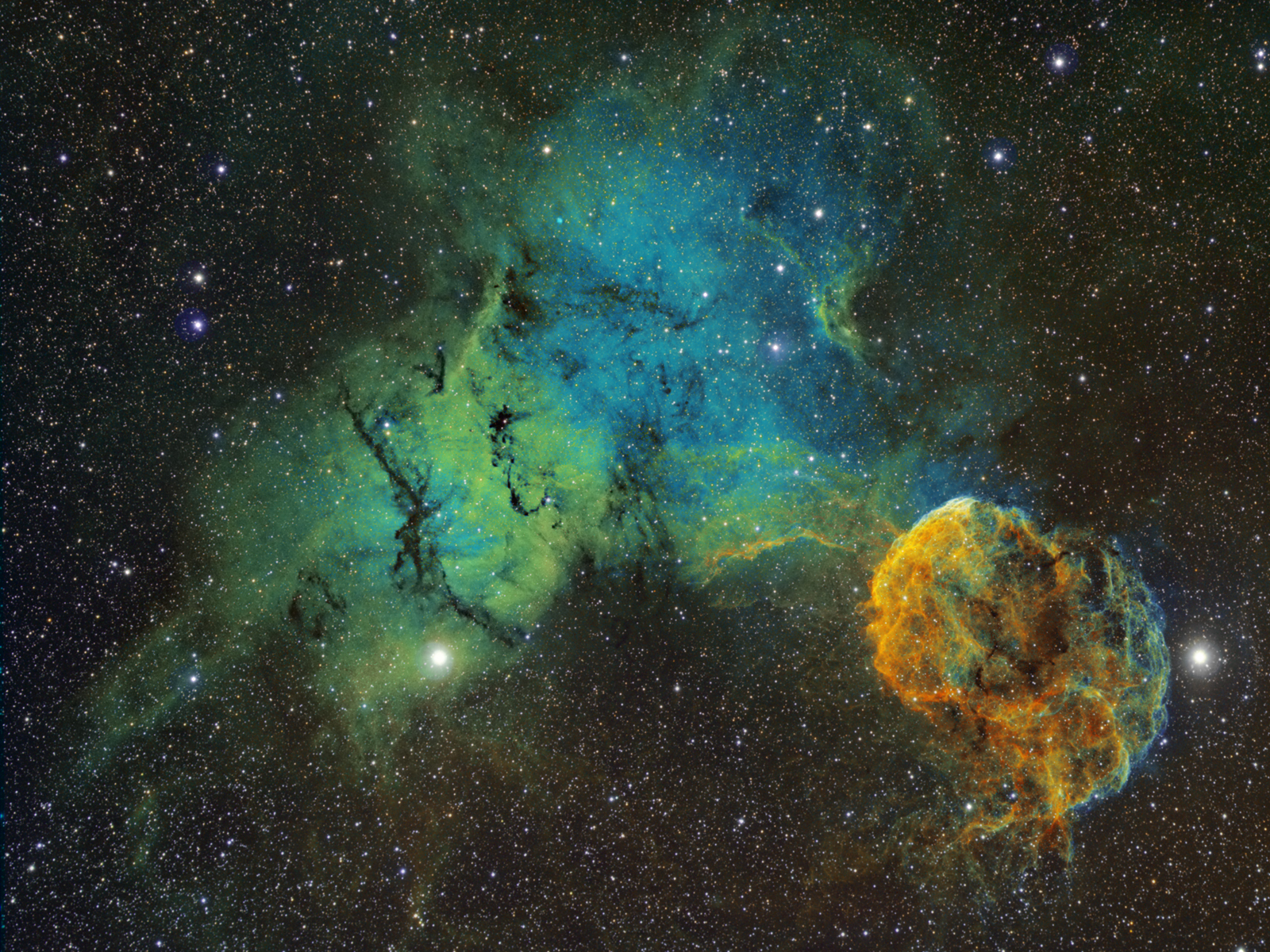
It turns out that option two is in fact true. Sh2-249 lies very close to IC443 (also known as Sh2-248). In Stellarium it is wrongly marked as reflection nebula and shares IC catalog number of 444, which is not true as it is Ha region. IC 444 is indeed reflection nebula a bit further away and not the same thing as Sh2-249. Central part of that region is filled with dark filaments. This APOD image shows complex and neighboring IC443

If we find any data on distances to both objects, and Sh2-249 turns out to be closer to us, or they are roughly the same distance (meaning Jellyfish is remnant of the star that was embedded in molecular cloud), then it is very likely that obscuring dark absorption part of Sh2-249 is in fact what you see in the image.
Jellyfish is roughly 5000ly. Let's see if we can find info on Sh2-249.
According to Simbad, distance to Sh2-249 is about 6556ly +/- 489ly.
Ok, not sure what to make out of this.
-
1 minute ago, Rodd said:
Those stars could easily be in front of the dark structure. Also, different parts of the explosion will cool at different rates--those dark structures are not empty space--they are cool gas and dust. Answer me this....if the dark patch in front of the glowing gas is empty space, why can't we see through it to the glowing gas behind?
Because glowing gas is not uniform ball. It has internal structure, and as such - it has filaments that are stretched out and areas of very low density. Don't capture enough signal - it just appears dark. There is probably faintly glowing gas that is transparent there as well, but it is not type of gas/dust that is blocking the light from behind (probably).
Let me find you another example of super nova remnant. That way you'll see what I mean. I could be wrong. This is not firm statement on my part - just trying to reason what it could actually be.
This is also SNR - Abell 85, we could similarly argue that dark regions in it are in fact dust clouds in front of it.
Here is better one as an example, look at this image (Simeis 147):
I've marked something that could well be dust cloud sitting in front of nebula - it looks about right.
Same feature in this other image does not look like cloud in front of nebula anymore:
Nor in this one:
-
Not sure how you concluded that.
Above attached images outline main difference between empty space and absorption nebulae - empty space contains stars, or rather you can see thru it to see stars although there is no other nebulosity behind so it looks black. With absorption nebula, nothing gets thru in visible spectrum, although you can observe in infra red or radio and see what is behind.
Jellyfish nebula contains stars in dark region, so it stands to reason that it is in fact empty space.
Important bit is that Jellyfish is super nova remnant, so not quite ordinary molecular cloud nebula that can contain dust.
There is remote possibility that there is dust cloud sitting in front of Jellyfish nebula and covering it, but I fail to see what would give it it's shape. Stars seen there could be foreground stars instead of background stars. Most nebulous things out there are either driven by gravity or stellar wind or some other process shaping it. Nothing remarkable in that region that could twist it like so.
I was searching for minimally processed image, ideally scientific survey type to see what can be concluded, but most images that I was able to find were heavily processed. In most heavily processed images that sort of feature will look darker than it probably is and smoother than it probably is (local contrast enhancement + denoising).
-
29 minutes ago, Rodd said:
I think I disagree with you if you are saying that the dark structures in the Jellyfish are not dark structures but the lack of Ha, OIII, or SII wavelengths. These structures are present in broadband images as well. To be clear--I use the tern dark nabula and dark structure interchangeably--perhaps that is my mistake. But if you are trying to show that there are no dark structures in the Jellyfish.....you have not convinced me.
Rodd
No, I'm not saying that there are not dark structures in jellyfish. I was trying to answer your question about names of "dark structures" or to be precise of dark / absorption nebulae.
Like I said, I believe that there are two types (maybe more) of dark structures - ones formed by something blocking the light from behind, and ones that just look like dark structure in the image because there is nothing there - empty space.
I'm rather convinced that empty space will not have catalog number / designation (why would it? after all, much of universe is empty space
 ). However, I do believe that dark / absorption nebulae, being actual things in space, although not emitting light but rather blocking it, will have designation as they are indeed objects of some sort.
-
I guess it depends on "type" of the dark structure.
Not all dark nebulae are the same, in fact - dark nebula (also called absorption nebula) refers to actual nebulous matter blocking the light from behind and creating dark appearance. It is dust and dense gas that is not excited and therefore does not shine in narrow band, but instead it blocks the light from behind - both of other nebulae/galaxies but also stars (and in fact anything that is lying behind).
You can have appearance of dark structure without dark/absorption nebula - if there is simply gap in gas cloud and there is nothing but deep space behind - which is of course black
.
You can distinguish the two by looking at the stars - dark nebulae tend to attenuate stars as well as other things, so they will be truly dark with almost no stars shining thru. Empty space will just look like a piece of background sky - so it will show stars regularly.
Here is nice example of dark nebula taken from wikipedia (lupus 4):
Note absence of stars in otherwise dense star field.
On the other hand look at jellyfish nebula in wider field (random screen shot from google image search):
Black space in nebula very much looks like that - place where nebula is not shining and not something that is actively blocking the light, stars don't appear less dense than in surrounding area.
-
Hi and welcome to SGL.
I'm not sure what the issue is. I mean, I can see that stars are out of focus slightly and yes, there is some tilt that I suspect is not the issue you are referring to.
You say that you are using focusing assistant and when you do focus exposure you have "pinpoint" stars. What happens next? Do you do exposure right away and get doughnuts or does it happen on some of the frames later on (after some time)? Do you slew your telescope between focusing and taking light exposure?
There are two things that can cause focus going off between focusing exposure and later light exposures:
1. Focuser slip. Depending where in the sky you point your scope and how the camera is attached (or rather where gravity pulls it) - you can have focuser slip (if for example camera is pointing straight up or down).
2. Temperature issue. With changing temperature OTA changes its length - materials expand and shrink with different temperature. This is enough to throw off focus, particularly on fast telescopes. If temperature drops rapidly over the course of the night, you might need to refocus on every hour or even half hour on fast scopes. Did you let your OTA cool prior to doing focus exposure? It might be that you are focusing while scope is still "hot" and not at ambient temperature. If so - it will cool rapidly and throw off focus.
Another thing that might be happening that you need to check for - is focuser lock mechanism. Do you lock your focuser after doing focusing exposures? (this sort of rules out case number one above). If so, tightening focuser lock screw can mess up with your focus sometimes, so you need to investigate if that happens, and when does it happen (tightening fast / slow, very tight or whatever). If it happens regularly, you might be able to figure out "offset" that you need to create - thus not focusing perfectly and letting lock screw "mess it up" just right
(yeah, I know, not a perfect solution, but can help until you sort out your focuser to eliminate this if it is indeed issue).
-
1 hour ago, geoflewis said:
If the master dark for a given pixel has a value of 300, with no photons reaching the sensor, then the "dark subtraction" process reduces the value of that pixel in the light frame by 300, assuming that 300 ADU of the light value is due to a thermal noise contribution.
1 hour ago, geoflewis said:5 minutes for Ha is not very long, so it is not surprising to me that you have a lot of 0 data after calibration. I usually shoot twice that for luminance data 1x1 and 8 minutes for 2x2 color.
Well, that is wrong reasoning as it does not include effects of bias (not all of ADU value in raw dark are from dark current). Read noise is Gaussian type of noise that can both "negative and positive" values around some DC offset (mean value). Poisson type noise / associated signal is always "positive" - meaning you can't detect "minus" photons - you are always going to get positive (including zero) detections on the pixel. Due to bias, once removed - even zero detections on the sensor will produce in some cases negative results.
But don't be bothered by all of that as you will include other software like APP in your workflow. Once you start imaging again, and using APP - you can examine your calibrated sub to see if there are in fact negative values and what is the number of 0-valued pixels. You will also see if you can see the difference in your stacks once you have properly calibrated subs.
-
 1
1
-
-
1 hour ago, dph1nm said:
Seems very over cautious to me! 8.7e- RN is equivalent to 75e- signal. A sky 5x this signal (not noise) - i.e. 375e- will only see the overall noise increase by 10% or so due to the RN contribution and I am pretty certain most people could not spot such an effect
NigelM
You are in fact saying that one should make sky signal being x5 "read noise equivalent signal", rather than sky noise being x5 larger than read noise. You are in fact making LP/sky noise sqrt(5) = ~x2.236 larger than read noise.
On 375e sky signal will have associated noise of ~19.36 (square root of signal). Sum of read noise and sky noise is in this case 21.23, so you are right, it is about 10% increase.
With other approach (making noise 5 times larger), one will in fact have: sqrt ( (1 unit)^2 + (5 unit)^2) = ~5.1 unit (where unit is read noise, and LP noise is 5 times that), increase in percents will be: 5.1-5/5 = 2% increase.
Like I said - it is arbitrary, but I would rather go for 2% increase then 10% increase, but you are quite right, a 10% increase in the noise will be very hard to spot for most people. Here is an example:
This is montage of two images of pure gaussian noise. One with sigma 1 and other with sigma 1.1. Data was linearly stretched (from lowest to highest value) after montage, so both images are stretched the same.
What do you think, is it left part of the field one with more noise or right part of the field?
-
1
-
-
1 hour ago, wimvb said:
This is the super pixel deBayering I described earlier. It is an option during image calibration in pixinsight. The only advantage this process has is that it doubles imaging scale and decreases file size. Only in the green channel do you get a slight increase in SNR. There is no improvement in detail, other than perceived.
It is a bit different then super pixel mode. In principle much of the results are the same, but splitting channels and stacking them separately has advantage over super pixel mode.
In super pixel mode, you are replacing bayer group (2x2 RGGB or what ever pattern is) with single pixel. If you look the at the position of sampling point, you will notice:
- red grid is "offset" by 0.5px, so is blue but in opposite direction (as no interpolation is done, it is in fact translation of the grid and pixel values remain the same). With this you are slightly misaligning color channels in resulting color sub thus creating slight blur.
- green is handled in such way that you take one green grid - green1 and translating it into one direction, while green2 is translated into opposite direction (again without interpolation) and then you take average - this creates small blur in green channel.
With split approach you avoid this. By registering all subs to same position - you avoid misalignment of color information, and green is no longer blurred (you do proper "shift" instead of "warped" translation of two subs). You have additional benefit of slight noise removal from interpolation process. If you for example use Lanczos kernel to interpolate images while registering them, you remove some of the high frequency components of the noise and you end up with smoother result.
-
1
-
-
2 minutes ago, geoflewis said:
In the meantime, I intend to write to the developer of ImagesPlus to ask him about the auto calibation process and why it is black clipping so may pixels. The software does include a manual calibration process, which uses the same calibration frames as auto. The manual calibration set up option also includes a dark scaling setting with the default set at 1.0. I found that when I set this to say, 0.75 then the number of clipped pixels was dramatically reduced to ~100. Even with dark scaling factor at 0.9 the 0 pixels was a few thousand rather than the sevearl hundred thousands at scaling of 1.0. I really don't understand what this dark scaling factor is as I can't find any explanation for it in the limited documentation that I have for the software, so I'm going to ask about that too. I wondered whether the setting in the manual calibration set up might carry through to the auto image set processing calibration, but that seems not to be the case the dark scaling factor getting reset to 1.0. Do you have any ideas what the dark scaling option might be Vlaiv? Here is a screen shot of the set up screen fyi...
Yes, it would be a good idea to ask about calibration process.
Dark scaling is something that you don't need but can use if you want to. It is used to calibrate with different exposure time darks. For it to work properly you need bias calibration as well.
Idea is as follows:
dark contains: bias + dark_current(time)
I put time in brackets with dark_current, because dark current intensity depends on time (linearly) - meaning well behaved dark current accumulates with time in the same way light signal does - longer the sub, more of there is (and in fact for doubling of the time - dark current doubles as well, so it is linear dependence).
If you for example shoot one minute lights and have master dark of four minutes - you can still calibrate your lights provided that you have master bias. Process would be as:
calibrated light = (light - ((4min_dark - bias)*0.25 + bias) ) / master_flat
Or in simple words - you take 4 minute master dark, subtract bias from it, divide what remains (only dark current) with 4 because you want to go from 4 minutes down to 1 minute, and "return" bias in by adding it.
Note factor 0.25 in above calibration equation - that is dark scaling factor, and it's value is ratio of exposure times - that of dark you have and lights you have taken and want to be calibrated.
If you use that factor without removing bias (without master bias) or on master dark of proper duration (or in fact if you use other number then exposure ratios) - you will get bad calibration.
In your case, you were just scaling down proper duration master dark (without bias removal) and you thus made it smaller. So if pixel in master_dark was for example 500ADU, and in original light was 490ADU (remember - noise can make it go up and down), without this scaling you will get -10ADU as calibration result (or rather you should get) - but software clips that to 0. If you scale your master dark by 0.9, then you have 490 - 500*0.9 = 40. This value is positive and it won't be clipped to 0. That is why you are seeing less zeros when using dark scaling, but I'm afraid such usage of dark scaling only leads to poor calibration and does not solve problem with histogram clipping.
-
2 hours ago, Ken82 said:
Interesting topic !
im currently trying to use a 071 cmos with 2x binning with my edgehd at f7. This gives me about 1” per pixel. Without the binning in APT I’d be at 0.5” pixel which is clearly over sampled.
From reading this thread am I doing something wrong by selecting 2x binning in APT ?
If you are doing binning in drivers (which I discourage for number of reasons) likely thing that is happening is following:
I'll explain on red channel, but others are the same. Going from left to right, and let's focus just on "one row", rest is the same, first 2x2 of red pixels is summed to form single pixel, then next 2x2 red pixels are summed to get next pixel, etc....
But these pixels are not put next to each other, but rather one "space" is left between them and then interpolated as with regular debayering.
Result of this is the same as I described above where you get x4 less width and height and then upscaled by x2 so you are effectively sampling at 2"/px this way (not that there is anything wrong with that, only minimum detail will be lost in very best seeing).
Btw, this is another way to bin color data and to still retain color (but it is similar to outlined above except it is upscaled x2 to make image larger - of the size one would "expect" from binning x2 sensor with that many megapixels - like in mono version).
If you don't want to bin x2 you can shoot non binned. You will still sample each color at 1"/px as I described above - if you extract channels as described rather than normal debayering. There is another way to look at all of that.
One part of pixel QE depends on effective pixel light collecting area. This is why sensors with microlens have better QE than those without. Lens helps increase light collecting area. "Regular" QE of pixel is in fact multiplied by ratio of effective pixel light collecting area / geometrical pixel area (pixel size x pixel size).
Maybe these images will help understand it better:
These are different sensors under microscope. As you can see lens is a bit smaller than pixel "square".
Why am I mentioning this?
Because you can treat color sensor for "speed" calculations in pretty much the same way you do with mono, but if you account for light gathering surface. In above example with 071 with your EdgeHD where sampling resolution is normally calculated at 0.5"/px, if you shoot color data unbinned, all colors will effectively be sampled at 1"/px as we have shown. But light collecting area for colors will not be 1"x1". It will be 0.5"x0.5". You can get around this by still using 1"x1" if you modify quantum efficiency of the sensor by taking one quarter of it. That is because red collecting area is one quarter of area of bayer cell.
Thus color sensors are at least 1/4 of the sensitivity of mono sensor. In practice we don't see that much loss in sensitivity because one integrates OSC data for x4 longer than mono. If you for example shoot for 4h - you will shoot each channel for one hour with LRGB filters and mono camera. With color camera you will shoot all channels at the same time - but for 4h each (thus spending x4 of time on each "filter").
-
1
-
-
If you plan on putting complete rig, and I'm not quite sure if this is one off thing for some public demonstration or will it be used multiple times, but I'll let you decide on budget in any case, here is what you should consider - in that particular order.
1. Decide if you are more interested in FOV or sampling resolution (you can sometimes match both). FOV will be more useful if you have list of objects you want to showcase - in that case look for FOV that will render all intended targets reasonably. Going by sampling resolution is more for "persona" use - chasing maximum detail in your captures if you like to examine structure / whatnot of objects you are observing.
2. Decide on mono vs color. Mono will be "faster" - render targets in less time but will obviously lack color. Color camera will be slower but will render targets in color of course.
3. Select CMOS sensor with best QE and lowest read noise you can find with sufficient number of pixels. ASI290 is quite reasonable for example, but you might like ASI178 if you want more megapixels.
4. Figure out what sort of focal length you need based on selected sensor size and either needed FOV or sampling resolution (target FOV size or target "/px).
5. Get scope with most aperture that has given focal length.
That is about it really
-
1
-
-
Color cameras can be binned of course.
Depending on type of binning applied you can either loose color information or retain it.
I meant to write one extensive post about different aspects of binning, and what I consider to be the best way to bin the data when doing images from multiple exposures (for other uses, other methods of binning might be more suitable).
Anyway, I'll briefly outline some things related to color imaging that people might not be aware (not much talk about it elsewhere) and explain how can binning both loose and preserve color data.
First thing to understand is that resolution of color sensor is not the same as mono sensor. It is a bit different, and we can argue that it is twice as coarse as mono sensor.
I've included image of bayer pattern for easier understanding:
Now with mono sensor, we think of resolution of the sensor as being "how much sky is covered by single pixel", expressed in "/px and calculated based on size of pixel. This works fine for mono sensors, but there is alternative way of thinking that is better when we want to discuss both mono and color sensor. Instead of thinking about "width" of the pixel and length on sky covered by this width - let's think about pixels being points (without dimension) and resolution being "distance" between these points. If we place one such point at the center of each pixel for mono camera, then distance between two points will be same as pixel width - so effective resolution is the same - no change there (two views are in this case compatible).
However when we apply "pixel" approach to bayer pattern of color sensor, we have a slight problem - look at red pixels in above image - there is a pixel, than a gap, then a pixel, then a gap (going in horizontal, but same in vertical direction). How do we "incorporate" these gaps in our thinking about resolution if we accept "pixel per sky area/length" approach?
It is much easier to think about sampling points (without dimensions, and only distance between them). In this case we can see that red color is sampled at two "pixel lengths" rather than one. Distance between sampling points is twice the length (and height in vertical) of a single pixel.
If pixel/resolution calculation for this sensor gives us 1"/px - red color will be actually sampled at 2"/px. Same is true for blue color. In principle we can say that same is true for green color, although it is not quite clear why (there is a bit of problem with X pattern of green pixels), but because both red and blue are sampled at twice calculated resolution, we should treat green as well. In fact if we "split" green into green1 and green2 where green1 and green2 are two respective pixels in 2x2 element of bayer matrix like this:
Here green1 being denoted as Gb and green2 being denoted as Gr, and threat each green component separately (namely green1 and green2 or as denoted in image Gr and Gb), we can see that each of those two components of green (although they are the same filter) are indeed sampled at twice "pixel size" resolution.
Now that we understand why is resolution of color sensor twice lower than that of mono version of same sensor, we can see further how we can do debayering of such sub and how we can do different binning on it.
First let's do bayer split. Most people think about debayering process as creating color image out of mono. It is perhaps better to think about it being "channel extraction" process. When you do it like that, you turn single color sub into corresponding R, G and B subs - which are in principle the same as if taken with mono camera and filter (apart from the fact that regular filters have different response curve and QE).
Regular debayering employs interpolation to fill in missing pixels and produces color sub of same dimensions (pixel count in height and width) from mono sub. Problem with this approach is that you are effectively "making up" missing values. It is done cleverly so that image remains smooth (like doing average of two adjacent red pixels to create missing value), but problem with this approach remains - you cannot recover missing detail. Image created this way will still have the same detail as image sampled at twice lower rate (which it in fact is) - you will get the same thing if you take image sampled at twice lower rate and upsample it to larger size (that is what debayering in fact is).
If you want sharp image (or rather sharper) from bayer matrix - you are better off splitting image into colors without resampling / debayering the regular way.
Easiest way to describe this process would be with following image:
First part of the process would be to split colors into separate "sparse" grids, and then next step (here denoted as interpolation because it explains regular debayering workflow) would be to "condense" those sparse grids instead of interpolating missing pixels.
This way bayer matrix sub is split into 4 smaller subs, one containing only red pixels, one with blue pixels, and two with green pixels ("green1" into one smaller sub and "green2" into another). Now we have color subs as if we took them with mono camera and appropriate filter with a small difference - sampling rate is twice lower (because of color sensor and bayer matrix) and you end up with twice as much green subs then red and blue (this is due to color bayer matrix being developed for day time photography primarily and eye is most sensitive in green and green response curve closely matches that of perceived luminance in human vision so having more green gives better SNR and definition in that part of spectrum that is more important for human vision).
Resulting subs will have half the pixels in height and width resulting in x4 smaller file.
After we do this - then we can bin each of those color subs further in software to increase SNR and decrease sampling rate. This way we preserve color information and increase SNR - however note that x2 binned color sub will in effect have x4 less pixels in height and width than original sub. This might look odd, but that is only because we are used of thinking in full pixel count for color subs from OSC camera, when in fact, as shown above you do have "half" of pixel count in both height and width for each color.
Of course when you bin raw image in the regular way - you add one red pixel, one blue pixel and two green pixels and you get single value, which turns to "mono" simply because there is no way to reconstruct what numbers you added together to get result (4 can be either 2+2 or 1+3 or 4+0 or in principle infinite number of different numbers can add up to 4 like -8+12, ... so when you take 4 you can't know what two original numbers are added together to form it).
-
1
-
-
13 hours ago, geoflewis said:
Is it possible that my flats and flat darks are the problem? I use an LED light panel for my lights and with the Ha filter the flat exposures were a fairly long 90sec, which I matched for the flat darks. Here are a single flat, the master flat (from 20), singe flatdark and master flatdark (from 20)....
I've taken a look at subs you attached, and they look pretty much ok, so I'm certain they are not to blame for zeros that appear in calibrated frame.
I do have couple of recommendations and one observation.
- Use sigma clip when stacking your darks, flats and flat darks. You are using quite a long exposure for all of your calibration frames and chance you will pick up stray cosmic ray (or rather any sort of high energy particle) is high. It shows in your calibration masters. Sigma clip stacking is designed to deal with this. Here is an example in master flat dark:
Now if that were hot pixels (like surrounding single pixels that are white) then it would show in the same place on master dark, but it does not (master dark has few of these, but at different locations / orientations).
- There is quite a lot of hot pixels that saturate to 100% value - these can't be properly calibrated, so you need some sort of "cosmetic correction" of these in your master calibration files. Such pixels will be removed from light stack by again using sigma clip stacking, but you need to dither your light subs (and I'm sure you do).
- I've noticed something that I find strange in your master flat, a sort of linear banding. Not sure why it is there, or if it has a significant impact on the image. Probably not, and it is probably related to manufacturing of sensor - sensor has slightly different QE in that area because of something.... If you did not notice this pattern in your final images, then it is all fine. Here it is what I'm talking about:
Does not look like regular vignetting as it has sort of "straight" edges (and not round) although it is in the corner where you would expect vignetting.
It is probably nothing to be concerned about - I just noticed as it looks interesting and I have not seen anything like that before.
Now on ImageJ - I've already written a bit on how to use it to do calibration, so maybe that thread would be a good place to start. I wanted to do a thread where I would describe full workflow in ImageJ, but it sort of did not draw too much interest so it slipped my mind after a while, and I did not post as much as I wanted, but I believe it has part on calibration. Let me see if I can dig it up.
Have a look at that thread - there is a lot written about calibration, and also a plugin included that will do sigma reject (which you will need for your subs).
You can try it out to see what sort of results you will get, but in long term - do look at specific software for doing it automatically like APP for example.
If you have any trouble following tutorial, please let me know and we can go into specific details.
-
I did not check it out, but I do have suggestion for further enhancements
How about adding "imaging" mode along side visual mode. There you can put calculations for FOV size, sampling rate, .... (actually have a look here for inspiration: https://astronomy.tools/)
-
50 minutes ago, Ken82 said:
Yea I realised this today. APT flats test was getting an ADU of 64000 with the simple white t shirt method. My flats panel is only 160mm and I’ve been trying to get some results with the edgehd at f7.
I may go back to using a refractor for a while until I’m comfortable calibrating this 071 as I’m trying to cross a few bridges at once.
Do use pixinsight Vlaiv ? What’s your process to calibrating ? I usually follow the light vortex tutorial which has worked wonders until now.
I tried PI once - download a trial, but found it too complicated / unintuitive at a first glance, so did not use it much (and the fact that price was a bit steep at the time), which in hindsight was a good thing - I started thinking about different processing algorithms and implementing my own stuff.
I do my calibration in ImageJ at the moment, but work on a small software that will do calibration. Doing it in ImageJ is just a bit more involved, but works and it's not overly complicated. I'll outline steps and details briefly.
- I use darks / flats / flat darks as calibration frames (no bias since I use CMOS sensor and bias is not reliable on my camera - that being ASI1600 v2). I also get as much calibration frames as possible (usually around 256 of each). My flat panel is rather strong so it does not take a lot of time to get one sub (just a few milliseconds of exposure - it takes more time to download a sub in SGP than to shoot it). Flat darks are the same settings as flats (meaning gain, offset, exposure length, temperature), darks are at the same settings as lights (again gain, offset, exposure length, temperature). Actually I set my offset at 64 and leave it there (specific for ASI1600 - other cameras can either have offset control but use different values, or have it set at factory without possibility of change).
- I stack flats with simple average. I do the same with flat darks. I create master flat by simply subtracting flat darks stack from flat stack. If I plan on doing any sort of measurement I "scale" my flats to 0-1 range. I do this by examining histogram and finding value at the peak of histogram (or doing average of top few percent of pixel values), then divide all values with that value. I'm not overly bothered about where histogram peak should be, but I do keep it in right half of histogram (so over 50%, probably around 80% or so). This is because again I use ASI1600 at unity gain, so it effectively works in 0-4000e region which is far from saturation value of about 20000e and it is certainly in linear region. I just make sure there is no histogram clipping.
- I stack darks with sigma clip method (it removes any sort of funny cosmic ray hits, and there has been some in my darks).
- Calibration after that is simple calibrated = (light-master_dark)/master_flat
- All operations are performed in 32bit per pixel mode, so first step I do is to convert precision of every file I'm working with.
-
1
-
-
36 minutes ago, geoflewis said:
I checked and there are no zero values in the single dark, where the minimum seems to be ~400 ADU. The minimum value for the master dark is ~500 ADU.
Yes indeed, darks look proper, here is histogram of single dark:
and here is from master dark:
Both look as they should - no issues with clipping, which tells us that offset is good for this camera and that is not the source of many zeros.
Now for light frames:
Sub directly from camera looks ok, here it is histogram of that:
But the histogram of calibrated sub does not look good:
As it shows clipping to the left.
I don't have master flat, so I can't do full calibration, but let's just do dark subtraction and see what the histogram of single sub should be, and measure background ADU value.
Ok, this is properly calibrated frame - it has nice gaussian curve with no clipping, and there are negative values present. I can now do measurements on it.
Background level now reads 38ADU - so a bit less than it did before (before it was skewed by improper calibration). Properly calibrated sub also looks "cleaner" than that with zeros.
There seems to be something wrong with your calibration workflow.
54 minutes ago, geoflewis said:Checking the calibrated same image shows a huge number of pixels with 0 ADU, so for sure the calibration seems to be making the difference. If calibration simple deducts the dark frame value per pixel this makes sense, as anything in the raw file with ADU <500 will move to 0 if the dark master has min ADU value of ~500.
You are right about subtraction of dark pixel values from light pixel values, but clipping at zero is not the proper way to do it - you can have negative values in the sub, and that is perfectly fine. I'll explain how this happens and why it is ok (as opposed to clipping it to 0). Master dark indeed can have higher values that light sub and again that is fine.
It has to do with noise and signal level. If something has for example 100e signal level, that means that average value of signal on very large number of subs is going to approach 100e. Every single sub will in principle have different value - some will have more than 100e some will have less than 100e, and on average it will be 100e. As you can see noise can go "both ways" - meaning provide both larger or smaller value than actual signal value.
Similar thing happens with darks. Darks contain bias signal (which has read noise) and dark signal which has dark noise. Light frames contain all of that + target and LP signal. In places where there is no target and in cases where LP is very low - like in dark skies when using NB filters - most of light frame background will be only bias+dark (same as in master dark). It will include a bit of LP signal, but that being low might not make much difference.
Now remember that read noise for your camera is 8.7e - that means that pixel value on every sub goes +/- this value (or rather that is one sigma, so it goes even more than that - in 99.7% cases it will be in range +/-3 sigma or about +/-26e). Master dark is stack of dark subs - so each pixel is closer to average value than single sub. For discussion purposes we can say that master dark has exact average value.
Light sub will behave as any other sub on background pixels (only dark+bias same as dark sub, and very little LP) so it will have either higher or lower value than this. If value is lower due to noise and LP signal is not strong enough to "push" it back over average of master dark, when you subtract master dark - you will get negative value. Negative value just means "no signal" and noise that "oscillates around 0", and sometimes it's positive and sometimes it's negative.
Now let's get back to why clipping at 0 is bad. Imagine you have 0 average value and some noise around that value. Average value of that noise will be - well 0, that means there must be negative values and positive values and those should balance out to get you 0. If you take all negative values and just "declare" them to be 0 - you shift the balance. Sum of such numbers simply must be higher than 0 and average of such numbers will certainly be higher than 0. You have made a change in recorded signal - it is not 0 any more but some higher value. Clipping of histogram changes recorded signal. It does so with all the pixels that have negative values - it does not do that with pixels that have all positive values (because their average is higher than 0). This means that you don't just add some offset, you are in fact altering your image and any altering of image can be considered noise. But this noise is not random, so it is bad kind of noise.
Moral of all of this - you should look into your calibration workflow and fix things. If you want, I can give you small "tutorial" on how to properly calibrate your subs in ImageJ (it's a free software for scientific image processing) in case you can't figure out what is wrong with the software you are using and your workflow.
Btw, I'm sure if you properly calibrate your subs and restack them you will find that your image is easier to process / nicer looking than previous version.
49 minutes ago, geoflewis said:Hi Olly,
Thanks for your observations. 0.43"/px is precisely why I bin 2x2 with the C14 and as you suggest I have considered 3x3, but never used that other than for plate solving where I actually use 4x4. My guide RMS is typically around 0.5"-0.6" total, with lower values for RA and Dec (typically 0.3"-0.5" each). That is clearly more than half my image scale of 0.85" when binned 2x2, so please could you explain the target of half image scale. As you will have concluded from my discussion with Vlaiv on this thread I really understand very little of the science of this hobby 😖. Up until now I've just guessed, but now I'm trying to better understand what I should be doing and why.
Although Olly mentioned this, I'll give my view of it (which I'm certain agrees with Olly's).
Guide RMS being half that of imaging resolution is just a rule of thumb / arbitrary chosen value that works well - much like above x5 as ratio of read noise to LP noise. In fact, same mathematical principle underlies both. Guide errors and seeing are sort of "noise" and add as any other type of noise (Square root of sum squares). That means - when one component gets small enough compared to other components it simply does not make much of a difference.
Sampling rate is often chosen based on average seeing conditions and aperture of the scope. Having guide RMS half of sampling rate (both in arc seconds) ensures that guide error will be comparatively small to that of seeing and therefore won't make much of a difference. Another way to think about it would be - if guide RMS is less than half a pixel, then "total" motion of scope relative to the star is still within that pixel for most of the time (Guide rms just looks at displacement, but displacement can be in both "positive" and "negative" direction, so if displacement is half a pixel then you won't "leave" pixel if you start at its center sort of reasoning).
This is why above is good rule of the thumb.
Just for completeness - same applies as with sub duration. Better guiding is always better than worse guiding (kind of obvious when written down like that
) - in the same way less longer subs is always better than more shorter subs (for the same total integration time), for the same reason but also with the same "property" that at some point difference is too small to be important for all practical purposes.
-
1
-
-
3 minutes ago, jambouk said:
I can only get it to run with FireFox for the moment and only with the inbuilt camera on the laptop, not another one via USB, but will try again tomorrow.
Try installing WDM drivers for USB camera (if it is ZWO camera) - software probably uses WDM type driver to access the camera.
-
That one is going to be tricky. Not in choice of camera, but rather in choice of software for viewing.
In principle, you want largest size CMOS sensor with largest size pixels and lowest read noise possible. 14" F/8 is going to have massive focal length, and you want your image to be sampled at no higher than about 1.5-2"/px.
FOV will also play a part - this is why you need large sensor. Let's do some stats on one such camera: ASI294
With 14" F/8 model you will have about 2850mm of focal length. Pixel for pixel it will sample at 0.34"/px, but since this is color camera - you can safely go for double that, so 0.67"/px. This is still far from target resolution, but luckily you can bin x3 and get almost exactly 2"/px.
Now let's see what sort of output we are going to get:
First FOV:
That is really tiny fov - we are looking at the "heart" of orion nebula, or about x3-4 smaller FOV than is needed to capture that nebula.
You will also be hard pressed to fit M81 inside FOV:
And in terms of image size, you will end up with about 690x470px, which is rather small, but could be all right for showing on lower resolution projector type device (something in WVGA 854 x 480 class - a pico projector for example).
Even if you add focal reducer FOV on such a large scope is going to be tiny and you will be able to get larger size image with larger sensor.
Going back to beginning of my reply - not sure if there is any software currently being capable of doing that level of binning for EEVA and that is major obstacle.
How about doing a bit different approach? What would be your budget and room for experimentation?
First of, I would add nice reducer field flattener to this scope to get large corrected field out of it. I'm assuming it is 14" RC type scope? x0.75 Riccardi FF/FR should provide corrected and fully illuminated field up to full frame sensor - meaning diameter of about 43mm. Let's check FOV of such setup:
Ok, a bit nicer FOV this time - I also left above FOV for comparison:
Still cropped Orion nebula, but much more "viewable":
Ok, that is about as large FOV as you will be able to get out of this scope. But how to get image out of it? Well you can go with above approach and do the similar (this time probably binning x2 after debayering with super pixel), or you can try different approach and use smaller sensor, but in order to use small sensor you will need couple of things - eyepiece with sufficient field stop and good lens for ASI camera and a system for connecting all of them.
If for example you want to use ASI290 type camera with above combination, I would think in following terms:
Sensor diagonal is about 6.46mm and that means that you need something like 43/6.46 = x6.66 reduction factor (or x0.15 reducer
) but we are going to do it differently.
You get Baader Hyperion Aspheric 36mm eyepiece - it has 45mm field stop so entire corrected FOV will fit inside. It also has threads for attachment - which is very good as it solves a part of attachment process.
This eyepiece gives about x60 magnification (this is important to remember as we are going to use it later).
Now let's calculate how to fit above FOV onto 290 sensor. Above FOV has width of about 0.94 degrees, so let's see how much arc seconds that is - 3384 arc seconds. ASI290 has horizontal resolution of 1936px so that sort of FOV will be sampled at about 1.75"/px (very good sampling rate for mono sensor in this role - and mono sensor will be more sensitive than color one as you will be capturing luminance only - but live viewing will be in black and white).
So far so good. But what sort of focal length do we need to be able to sample at 1.75"/px with 2.9um pixel size? You need about 685mm of focal length.
But remember that image that we have is already magnified x60 because we used 36mm eyepiece with this scope, so we need x60 smaller focal length. That is about 11.4mm lens.
So in this setup you will need:
x0.75 Riccardi reducer/flattner with M82 thread capable of correcting up to full sensor diagonal (about 43mm)
Baader Hyperion Aspheric 36mm eyepiece
ASI290 mono camera (or camera from some other vendor with same sensor)
and
11.4mm lens capable of illuminating 1/2.8" sensor size and having very good sharpness.
And btw, you connect them in the order I listed
with distance between reducer and eyepiece being important, and distance between eyepiece and camera lens being that of eye relief of eyepiece (which is 19mm).
In the end a disclaimer - I've not done above to confirm it is working, but by all accounts it should. If you have the time and resources to test it out, then I would advise you to give it a go, it is probably the best bet to get anything decent for EEVA out of that scope, but it indeed requires quite a bit of money to test out and fiddling about, so probably not so interesting to try out.
Just a final note, with this sort of arrangement - being scope, ep, lens, sensor - you don't need any fancy binning so any EEVA software will work.
-
1
-
-
2 hours ago, saac said:
For the star I used a globe style lamp
I was just thinking about this, and this is excellent way to do simulation to get proper results. Have not thought about it previously, but this thread gave me food for thought.
I was under impression that star is providing uniform illumination (or rather I always thought of stars in two terms - either single point of light or uniformly lit disc), but above transit graph shows it is not the case. If one wants to properly simulate this and get exact curve - this needs to be taken into account.
I'm talking about this region of graph:
It shows section of the transit where planet is fully "inside" stellar disc. Why should there be dip in this section of the graph? If you observe purely geometrical aspect - you have two surfaces - that of the star and that of the planet - both circles, and "total light emitting" surface is equal to their difference. However this line of reasoning does not include the fact that amount of emitted light from the star depends on angle on its surface!
I'm sure I've seen this effect before, but have not payed attention to it, and here is an example of it:
If you look at this Ha image of our sun - you can see that it is not uniformly lit (disregard features and look at average brightness of surface). It is brighter at the center than towards the edges. Planet disc near the edges will remove less light than that close to center of the disk - that is why there is "dip" in curve.
You should either use image of the sun on a black background evenly illuminated with some source, or as suggested - globe type lap as it should provide similar effect.
-
2
-
-
5 minutes ago, Alien 13 said:
I do have another question regarding alternative visual backs, the Mak has a huge range of back-focus so is it better to use a short adapter meaning the main mirror is further down the tube or a much longer one that puts the sensor position at a similar point to that obtained if you were using a diagonal and eyepiece?
Alan
Good question. I know that SCTs have issue with spherical correction and back focus, or rather there is spherical aberration if you focus far away from "ideal" focus point. Not sure if it applies to MCTs as well.
Another important point is if focus position is optimized for stock 1.25" diagonal and whether you should calculate things from that point.
-
1
-


A friend has a question
in Getting Started Equipment Help and Advice
Posted
Huh, that one is tricky.
Not sure if you will reach any sort of consensus on that question. Some people prefer newtonian (dob mounted), and others SCT on either alt-az mount or EQ mount.
Each one has pros and cons, and only if you examine pros and cons will you be able to decide which one is better suited for your you (or your friend, whoever is choosing).
In optical terms, well, they are of the same aperture and in principle newtonian will have very slight edge if both are made to same standard of quality (smaller central obstruction, one less optical surface that can introduce aberrations / light scatter, SCT have some spherical aberration when you focus away from perfect focus position - which is possible by focusing mechanism as it moves primary mirror instead of eyepiece).
However, most sample to sample variations in both scopes have larger optical quality difference than those listed above.
I can start list of pros and cons, and others will probably add to each from their own experience.
Newt (dob mounted) pros
- price
- wider field possible
- faster cool down time, less issues with dew (no front corrector plate)
- above mentioned slight optical edge (which might not be there in actual samples, but I list it anyway because I'm in newtonian camp )
)
Newt cons (again dob):
- harder on eyepieces (but really not that much) as it is F/6 vs F/10 of SCT
- harder to reach planetary magnifications (often barlow is used)
- Bulkier / heavier
- constant nudging may bother some people (although you can get either goto dob, or eq platform for it, or alternatively mount dob on EQ mount or motorized Alt-Az mount. If you put it on EQ mount - Eyepiece will end up in awkward positions most of the time so you will have to rotate the tube)
STC pros (I'll try not to repeat above ones):
- not sure what to put here that has not been mentioned, but probably weight / compactness / portability of OTA (although I did mention that newt con is that it is bulkier/heavier than SCT).
- comfortable eyepiece position (but again same in the dob mounted newtonian, and looking near zenith is easier with dob mounted newt).
SCT cons:
- might suffer from focus shift (since it is focusing with moving mirror, mirror does not stay perfectly parallel the whole time so image can sometimes shift as you focus, particularly when you change focus direction due to slight backlash in focusing mechanism).
Ok, I'm having trouble describing SCT (I'm really not a fan, and I never used one and I would personally choose dob instead) so someone who has one and likes SCTs should step in to complete lists.