


vlaiv
-
Posts
13,106 -
Joined
-
Last visited
-
Days Won
12
Content Type
Profiles
Forums
Gallery
Events
Blogs
Posts posted by vlaiv
-
-
I don't think that single piece of software can do it all.
There is a bunch of alternatives out there as seen by previous posters (everyone has their own favorite piece of software for particular purpose). I can give you decent freeware / open source list that you can try out:
- SharpCap for planetary capture
- Pipp for manipulating planetary videos (calibration, pre processing, etc)
- AutoStakkert for stacking planetary images
- Registax for wavelets sharpening of planetary images
- NINA for long exposure capturing (not sure if it handles DSLR though)
- Deep sky stacker for calibration and stacking long exposure images
- Gimp for processing (of both planetary and long exposure images) at the end
-
 2
2
-
-
Nice image.
6 hours ago, mikemabel said:I am thinking about buying a ZWO 533MC pro to replace the 183 or compliment it
I would not rush into that. Although 533MC is nice sensor I don't think it can replace 183 since latter is mono.
From what I can see, you used ST102 as imaging scope, right? Maybe first fiddle around with it and gear that you already have. Software binning will produce better SNR as you are slightly oversampling because you are using short focal length achromat (colors are not in focus and that produces blur). Using yellow filter will help much with star bloat as it will remove most of violet part of spectrum.
-
18 minutes ago, Leon-Fleet said:
Thanks for this. I think the Evostar 72 is closer to my budget right now.
Depending on size of sensor, you might want to factor in a field flattener as well - and if looking for wide field setup - go with one that is reducer as well.
-
I think that you want something like this:
or perhaps a bit better version (not optically, but mechanically as it has sliding dew shield and 2.5" R&P focuser):
-
1
-
-
Although many will warn against such viewing - I'm certain that most will agree that some observing is better than no observing, so by all means - if that is the only way, go for it.
I think it is just a matter of managing expectations, and making the best of circumstances - like in your case, if open window is needed to bring room to close to ambient, and similar.
It would be good if you could give us comparison - how much degradation there is compared to being outside (in same / similar conditions).
-
2
-
-
25 minutes ago, joe aguiar said:
that link doesn't really say what zone it compares to the coloured zones but that's ok ill figure it out now
so 9 should be a white
8 a red
7 a orange
6-yellow
5-green??
so your a green zone? if so that's great. I have said in many other posts that in a green zone is where the really fun sky starts begins.
iam on a computer now so now I can see your sig its a 4.5" scope. ok its not huge but since I think your in a decent sky conditions I think you can see a lot.
the number one thing even if your in the white or red zones or in any colour zone is to get away from any light sources like streetlights, house lights, portch or garage lights, by doing this you can have your eyes get dark adpted and you can and will see more. Most of my life iam in a white zone which is the worst zone, but I also have been to just about every zone and observed from all zones cept the black zone.
only issue u may have is your scope being 4.5" has a focal length of 1000x mm fl which means it has that barlow in the focuser so views may be softer, also it will be hard to get low power views if those large extended objects.
joejagur
Both 9 and 8 are considered white zone, 7-6 is red, etc. In fact there is neat "conversion" diagram that one can use to switch between different designations (like Bortle scale, color scale, NELM, SQM and such):

In any case Bortle 5 ranges from about SQM 19 to 20, so that gives good indication for observable surface brightness. Add 8.89 to magnitude in arc minutes squared - listed in Stellarium for example and if that number is above 20 you will be able to see some of that particular DSO - but that will depend on position in the sky and transparency on given night. It will also depend on distribution of light as magnitudes in arc minutes squared are usually average magnitude for object - galaxies with prominent core will be easier to spot as core will have larger brightness than what average suggests.
Back to original question - you should be able to see quite a bit, just adjust your expectations on what it should look like. In Mag18.5 skies (that is border between red and white zone, so bortle 7-8 border) with 100mm scope I was able to observe a number of M's - mostly globular and open clusters, but some nebulae as well and a couple of galaxies.
27 minutes ago, joe aguiar said:on another note I have once read that bortle zone and what u can see and it seems wrong and that's y I don't use it and prfer the colour charts better. for instance in the red zone it was m31 can be seen with your eyes and that's wrong I cant even see that in a yellow or maybe a green zone. m31 is HUUUGE so its light is spread out. and I think it also says somewhere where you can her m13 which I have never also seen it yet my eyes is 15/20 based on the last eye test.
I'm at above border of red/white and I can see M31 with averted vision on night of good transparency, so red zone it should not be a problem most of the time. With 8" scope I once observed dust lanes from same location - mind you it was night of very good transparency and M31 was near zenith.
-
If you value speed of capture - just keep mono camera, it will be faster than alternative OSC (faster in terms of reaching set signal to noise ratio - less imaging time for same results).
On the other hand if you prefer "ease of operation" - then switch to OSC. However, do keep in mind that OSC + Triband filters is not going to produce as good results as mono + narrowband on nebulae.
-
1
-
-
I would like to point out something here that might not be obvious (for me at least - it took some time to realize it) - larger sensor is faster sensor

Most of recent talk about speed of setup was in terms of pixel scale, and I'm to large extent guilty of being promoter of such view. It is in fact matter of aperture at resolution. However, most of the time that discussion neglects one important thing - resolution is not set in stone. It is for the most part if we follow traditional processing workflow - but then again, why should we, if there is alternative that allows for more flexibility?
Before I explain what I meant with above, we need to assert one observation - when doing software binning of pixels, only difference between camera with smaller pixels and one with larger pixels (everything else being equal) is amount of read noise. There is rather nice way to control impact of read noise on the final result - exposure length. Longer exposure length comes with it's challenges (like guiding, probability of wasted data, etc ...), but in principle one can control impact of read noise.
Back to the story of faster sensor. If we have larger sensor - we can use larger scope (both aperture and focal length) to cover same FOV. If we control our pixel scale - for example thru fractional binning or similar techniques, we can image - same FOV at same resolution (in terms of "/px) using larger sensor on a larger scope. Larger scope will gather more light - resulting SNR will be better with larger sensor. Larger sensor is faster (it does hover mean certain processing techniques, being aware of read noise management and pairing it up with suitable telescope for target FOV and matching resolution via suitable binning).
In that sense 294 is faster than both 183 and 533 (at a small price premium).
Just to add - I'm in general not overly concerned with amp glow in CMOS sensors - from what I saw, it calibrates out and level of noise injected is comparable to read noise level which is rather low on CMOS sensors anyway.
-
1
-
-
6 hours ago, sharkmelley said:
I just accidentally found a document that defines gamut of a sensor. See section 2.1:
https://corp.dxomark.com/wp-content/uploads/2017/11/EI-2008-Color-Sensitivity-6817-28.pdf
So contrary to what I thought, the concept does exist!
Mark
That paper pretty much describes what I intended to do. There are some difference though. They deal with daytime photography so illuminant needs to be taken into account.
With AP we don't need to worry about that aspect - we can treat all light as coming from a light source (to some extent even reflection nebulae although they don't generate their own light - there is simply no way to illuminate them with another type of light) that has precisely defined spectrum.
We also have a way of standardizing transform matrix between sensors. There is a couple of ways to do it, but most obvious is to derive transform matrix for a range of black body objects in certain temperature range (star colors). We can also include some "standard" narrow band lines like Ha/Hb, OIII, SII and such in our set used to compute transform matrix. That should give us "standard color card" for color calibration.
-
1
-
-
Hi and welcome to SGL.
Planetary imaging is rather different than both daytime photography or night time DSO astro photography (whether it is wide field - like Milky way shots that you enjoy or closer up).
DSLR type camera is not ideal for planetary imaging, and yes, you want long focal length optics to be able to show any sort of details on planets. You will need at least a meter of focal length to do that (people often use barlows when having shorter focal length scopes to get enough focal length).
You don't need particularly large mount to satisfy your needs. Small compact scope will be good for planetary / lunar. Take a look at Maksutov telescopes or SCT. In smaller apertures up to 5" these are lightweight and can be mounted on really simple mounts (EQ3/EQ5 class mount and even compact travel mounts like AZGti). For planetary imaging unlike for DSO imaging you don't need very precise mount either since you'll be using very short exposures and stacking. For milky way shots, you can just use camera + lens combination attached to this tracking mount.
Besides above light weight mount, you will also need planetary type camera. Something like ASI224 or similar.
-
32 minutes ago, Rob Sellent said:
Thanks guys for the great explanations. In particular to @vlaiv and @davidc135for patiently going through this.
If I've understood correctly, for a appreciation of these type of graphs would it make sense to assume that the nearer to 0 better is the RMS and Peak to Valley (P-V) criterion and nearer to 1 better the Strehl ratio? Together indicating a flatter wavefront 3D image?
I also recall Dob guys - especially when considering buying a new mirror - suggesting that when evaluating potential optical systems it's a good idea to look for a pair of numbers, for example: 1/6 wave = .93, 1/7 wave = .94, 1/8 wave = .95, 1/9 wave = .96, 1/10 wave = .97, or something like that. In this case, I imagine that the wave fraction is related to the P-V and the decimal number to the Strehl ratio. Again, better the optic flatter the wavefront, lower the fraction towards an ever smaller portion and higher the decimal towards 1?
Indeed. You can think of P-V as difference between lowest point on a map (sea level) and highest mountain peak. It tells you what is the range of values on wavefront but it does not tell you anything about what the relief is (single mountain surrounded by ocean or something else). RMS is akin to "average terrain level", in the same sense guide RMS is average error of guiding (it is not average displacement as that would be 0 because any error in +RA would cancel any error in -RA, and similarly in DEC).
Strehl is very good indicator of optical performance as it deals with energy and that is what we see.
In any case, P-V and RMS of 0 and Strehl of 1 represent perfect optic - flat wavefront.
1/6 wave means exactly that in P-V - meaning that max difference between two points on wavefront is less than one sixth of wavelength. It roughly corresponds to 0.93 Strehl. If low order spherical aberration was only one present and it had magnitude of 1/6 waves then Strehl would be 0.93. Similarly goes for other values.
In some cases aberrations can sort of cancel a bit out - look at first report. P-V for that scope is 1/5.6 but Strehl is 0.97. Now if scope had P-V of 1/5.6 and only aberration present was low order spherical aberration - strehl would be worse than this.
It is similar for relation of PV to RMS. In above two diagrams you have same P-V error, but different RMS errors as contribution of aberrations is different.
Mind you, if you get above report for newtonian mirror - that is not the whole story as you need to account for secondary as well. Secondary mirrors as well as diagonals have usually 1/10 or better surface, but since things compound that error can be actually beneficial or can make things worse - depending on respective surfaces.
Same goes for lens in refractor. Aberrations that are not symmetric can somewhat cancel out between elements and rotating lens elements can affect final wavefront. That is the reason why lens elements are marked for orientation. If you rotate them, you can actually make things worse as aberrations that canceled out start "reinforcing" instead.
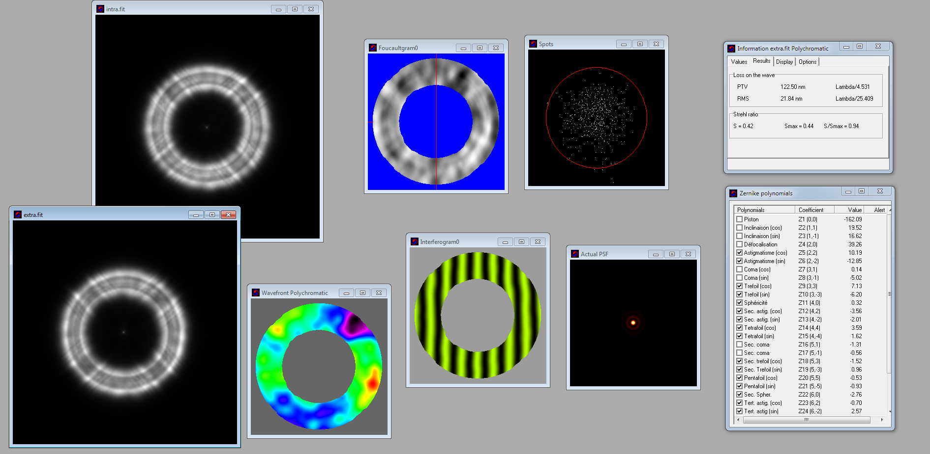
If you are interested in doing such report yourself, there is a way to do it. It requires planetary type camera or guide camera and a piece of software.
Process is as follows: you take images of defocused star (both in and out focus), stack them in certain way and import into WinRoddier software for Roddier analysis. Software does it's magic and you get something like this:
Above is test for my RC8 scope. I'll probably repeat it at one point just to verify results and also make sure collimation is spot on this time (not sure about last measurement).
I'm currently fiddling around with Zernike polynomials and trying to figure out how I would implement above software (already have some ideas).
Both Aberrator and WinRoddier might be a bit outdated software and I think astro community could do with the same (or enhanced) functionality.
-
4
-
 1
1
-
-
1 hour ago, jetstream said:
Also the best test report includes a sample of the many actual pictures, not just computer generated synthetic interferogram images
This is debatable, and it depends on technique used to asses wavefront. If interferometer is used then yes, it should include image, but interferometer is not always needed to determine above.
2 hours ago, Rob Sellent said:rom time to time when discussing a scope's optics or performance, I often see folk posting up optic reports. The problem is being a bit dim witted, I just can't make head or tail of them.
As pointed above - probably single interesting piece of data on such report is Strehl figure at particular wavelength.
I'll just do a brief explanation on what is going on for all interested (and partly because I'm actually rather involved with that topic at the moment
) :
All tests are done on optical axis, so this sort of report is only giving you idea of how the scope will perform on axis - it tells you nothing about off axis aberrations (which also depend on telescope design). Principal idea is that wavefront from a star (point source - single point along optical axis) is arriving at telescope aperture perfectly flat - uniform.
After telescope does it's thing and focuses light to a point - any optical "defects" of particular telescope act as if someone "twisted" that wavefront. Above colorful diagram titled : Wave front is displaying 3D image of wavefront phase (you can think of it as how much is rest of wavefront late with respect to point that first reaches aperture of scope).
This does not show surface of your mirror or lens or whatever! It relates to light wavefront.
Perfect flat wavefront will create perfect image that telescope aperture is capable of delivering. Any bending/ripple in that wavefront causes image degradation.
That is all you need to characterize performance of the telescope (on axis) - wavefront. It defines PSF (or image of the star with perfectly still atmosphere), MTF or diagram that shows how higher frequencies get attenuated and basically all other info on that report.
Any sort of deformation of wavefront can be characterized by set of functions (their sum) - called Zernike polynomials. Many of those polynomials correspond to a certain optical aberration or other effect on telescope. For example tilt and defocus (removed in this report because they are not inherent in optics) - represent angle of incident light (either star that is not on optical axis or tilted focuser / sensor) and actual defocus (focuser distance to ideal focus position).
Then there are astigmatism, coma, spherical aberration, etc ... All of these are represented by particular Zernike polynomial.
It's a bit like decomposing a vector into unity vectors (3X + 7Y + 1Z sort of thing) - so does wavefront decompose into these Zernike polynomials. Those aberrations that are not symmetric (tilt, coma, astigmatism) have both angle and intensity, while symmetric only have intensity (defocus, spherical, ...)
For further info - check wiki page: https://en.wikipedia.org/wiki/Zernike_polynomials
These figures are reported on the left. If one had complete decomposition to Zernike terms, one could reconstruct wave front of that particular telescope, but you would need more and more terms to get more precise description of wavefront - here in these reports only first few terms are recorded so it is only coarse representation of recorded wavefront.
-
5
-
1
-
-
2 minutes ago, gorann said:
But there are some great and relatively fast triplet apos with a single ED lens. Like Esprit 100 f/5.5; APM LZOS 130 f/6; CFF 140 f/6.5; Astro-Physics 130 f/6.3 (at least they do not advertise double ED elements).
I do not think the new TS 140 f/6.5 has a flatter field since they seem to recommend the same flattener/reducer (TS 0.79x 3") as for other telescopes, and they do not claim a flatter field.
There is more to objective lens than just color correction and field curvature. How does it behave off axis for example.
With all spherical design of the lens - you have following parameters (I could be wrong at this, so happy to be corrected): radius of curvature for each surface, thickness of each element, spacing between elements and refraction index of each element.
You play with those to get characteristics of your scope - color correction, correction of aberrations on/off axis but also there is one more point - tolerance. You need to know how much can manufacturing process deviate from ideal figure or thickness or spacing to still be within optical requirements that you set as a designer. Different combination of above parameters will have different level of "resilience" to errors.
I suspect that as manufacturing process is being automated - optical designers need to consider what sort of errors they can expect from machines doing figuring as well as tolerances on glass purity and account for those in their design process. On top of all of that - you need to be cost effective and have a market for your product.
Btw, I believe that we are pretty much at stage where computer can do it all - just wonder if software has been written for it - you input available types of glass, expected manufacturing errors, parameters of scope (possibly a few more specs like cost and time to grind/polish) and hit "optimize" button - and software gives you optimal solution
- if it says to use two ED types of glass - who are we to argue -
Probably best option would be to go with ASI385.
It has larger pixel size (same as ASI224 - better for small DSO) and has very low read noise. It is also larger sensor than 224 - again better for small DSO.
You don't need reducer / field flattener on such a small sensor, but if you use one - you will have larger FOV which is a good thing for DSO imaging.
Worth checking out is astronomy tools FOV calculator with specific combination of scope / sensor:
-
I've read this warning many times - it is often written on TS website along Ha solar gear - like this:
At some point I thought that Daystar quarks and their high return rate had something to do with this. Solar telescopes are shipped with good packaging - meaning a lot of styrofoam and such which is insulator. Quark eyepieces are shipped in regular small boxes and probably not well insulated. If shipment is in winter time or cargo is carried on an airplane - high altitude / low temperature, and I doubt that cargo bay is heated - this could lead to item being on lower temperature for some time.
So yes, that is a hazard that needs to be addressed. Don't know how it relates to blocking filter - it is often quoted for Fabry Perot filters - which use oil, so air spaced ones should be fine?
-
Not sure if there is proper answer to that question.
If you want to get realistic colors from your sensor, simple scaling is not the best way to do it - it is approximation. In fact, even more "sophisticated" methods are still approximation to some degree.
For better results you want to use color conversion matrix rather than simple scaling. Simple color scaling is a kind of color conversion matrix - but only diagonal one.
In any case, to determine suitable scaling - you can use a single star in your subs. Find a star of certain stellar type that will be your "white point". Probably best stellar class for this is F2 (non of the stars is pure white, some recommend using G type, although those are yellow stars, and some will use A class - that is bluish star). Take image of that star and compare intensity of each color - and that way you will get scaling factors (one that you should use to get star colors to be 1, 1, 1).
-
49 minutes ago, gorann said:
Does anyone know if there are any advantages with two ED lenses
I think it is best compared with eyepieces - you can get very good eyepiece with three of four lens elements. But if you want large AFOV, good eye relief and correction to the edge - you need to go with 6 or 7 or maybe even larger count of lens in a design.
Often wondered why there are no triplets made out of "regular" glass types as opposed to ED types and more exotic types. It all comes down to specs of the scope you want to build - what size of aperture you are going for and what F/ratio you want to achieve (probably even how flat field you want to get). One could probably design very good triplet at something like F/12 from regular glass types - but what would be the point? You can almost get very good color correction with achromatic doublet at that F/ratio (small aperture) and certainly with ED glass - although up until recently there were no slow ED scopes (there is now F/11 ED 4").
Combining more exotic glass types in triplet let's you optimize for particular scope design - fast with large aperture and relatively flat?
-
1
-
-
I think we have established a standard for scatter control here
-
 1
1
-
-
I do get that some people prefer such scopes and might find this interesting, but not really my cup of tea.
For AP applications - I can list few alternatives that will be cheaper than this and probably as effective (if not more so) - like already mentioned hyperbolic newtonian, or something like nice 6" Mak-Newt if one does not fancy diffraction spikes.
For visual, I think people would rather choose something at F/7-F/8 if choosing doublets?
-
I was playing around with simulation of seeing effects and have very viable model in reproducing seeing effect - apart from one thing - creating seeing wavefront disturbance.
Here is quick breakdown of technique used:
I created "aperture" and random seeing disturbance:
Aperture is wavefront intensity with 1 being in aperture circle and 0 elsewhere.
Next I took very small image (24x24) and created Gaussian noise on that and then enlarged it to 512x512 image - this gives rather nice looking wavefront error (although probably away from accurately representing seeing wavefront):
This image should be interpreted as phase of wavefront.
Next step would be to compose two images - real and imaginary by combining phase and magnitude (which is simply sin(phase)*aperture and con(phase)*aperture):
Here it is side by side:
And of course, last step would be to find FFT of this complex wavefront representation and look at power spectrum of it:
This image has been gamma corrected to better visually represent star as it would look when observed.
It gives rather "credible" looking seeing distorted star. Depending on "granulation" of wave front and intensity of phase shift (first is controlled by size of base gaussian noise image and how much it is enlarged / it's relative size compared to aperture, and second is controlled by sigma of gaussian noise - it is phase shift at anyone point in radians) we can get different seeing levels like this:
(fine fluctuations in wavefront - like when using large telescope)
Or very decent seeing - second ring defined but broken in few places.
However, I'm sure that above generated seeing wavefront is not accurate representation of seeing wavefront. It probably has different power spectrum than average seeing that we encounter.
Does anyone know or have an idea how "accurate" seeing wavefront can be obtained (in terms of phase). Further more, how would one go about it's time dependence. I was thinking along the terms of multiple layers moving in different directions where one can define some sort of cell and combining those in some way.
Much like if I were to make multiple images with gaussian noise and then slowly shift them and morph them and somehow combine them?
I know that ultimate solution would be to do something silly like running simulation of Navier Stokes equations for 20km of atmosphere or similar - but let's go with next best thing, shall we?
-
1
-
-
3 minutes ago, DKNicholson said:
Using a 2" Antares x1.6 Barlow into a 1.25" filterwheel then camera, curiously led to noticeable vignetting where I had hoped it would help avoid it. So whether the vignetting was a result of that particular Barlow or just an inevitable result of using a Barlow, I don't know, but it is perhaps something to watch out for.
Barlows can vignette depending on their design and size of sensor.
In order to avoid vignetting it's best to use barlow that is meant for photographic applications - like Baader VIP barlow. It is designed to illuminate full frame sensor according to specs.
Of course, depending on how much vignetting there is one can either crop or use flats to correct small amount of vignetting.
-
Very nice indeed.
I have couple of suggestions for you if you are up to it.
- Try doing a bit of frequency restoration on your image - using wavelets transform like it's done in planetary imaging. This will make rather noisy image but rate of expansion should be easier to see.
- Maybe do calculation vs measurement on your image?
We have approximate distance to the object and measured expansion rate of 1500m/s - it's rather easy to calculate what sort of angular size difference there would be in 20 years. You can then compare that with measurements from these two images - measure difference in pixels and convert to arc seconds from sampling rate of your system.
-
2
-
-
10 hours ago, bluesilver said:
Thanks again for the reply.
I am at least familiar with the part you mentioned recording video rather than taking long exposures and then using the software to stack and edit that recorded footage.
Familiar in the sense of watched the videos and the different software that people use.
I have kind of gone around it backwards in that regards on things.
I will have a look at those two cameras that you have mentioned, appreciate that.
Is there much differance between the two cameras, ZWO AS1224MC USB3.0 Colour Astronomy Camera, and ZWO AS1385MC Astronomy Camera
From what i can see it that the only real differance is that the AS1385 has more pixels and is basically the updated version of the the AS1224
Sound like i could be better of first getting one of these cameras and see how it goes with the Dob first.
Appreciate all the advice.
When choosing planetary camera there are couple of things that are important:
- good QE. This is of course important for every application, better quantum efficiency means better SNR in same exposure time. This can be compensated in deep sky AP by using longer integration time (shooting for 5h instead of 4h for example), but not in planetary - where system is dynamic and you have limited window for data gathering (planets rotate and if you shoot too much you will have rotation blur - there is a way around that by "derotating" videos, but still, there is time limit on how much data you can gather).
- fast readout time. This is essential. In planetary AP one uses very short exposure times - couple of milliseconds. This is related to coherence time for given seeing, but in general it is below 10ms most of the time (only very good seeing provides coherence time larger than about 10ms). This means that number of captured frames will be limited by readout speed rather than exposure length (for 30ms exposure you can only do about 33fps, but with 5ms exposure you can do 200fps, and if camera supports only up to 150fps you will be loosing about 1/4 of the frames because it can't download them fast enough).
- read noise. This is also essential for planetary AP. Difference between one large exposure and stack of small exposures that have same total integration time as large exposure differs only in read noise. Read noise is only kind of noise that does not grow with time and is tied to single frame readout. When you gather tens of thousands of frames per recording - each one will have read noise associated. This is why you want your read noise to be the least possible.
Above cameras have these characteristics, but they are not only possible options. ASI290 is also rather good and available as mono version. ASI178 is also decent camera.
I'm listing only ZWO cameras because I know their model names, but you don't have to choose their cameras - other vendors also provide models of cameras with these sensors.
Mind you, good planetary images can be recorded even with "entry level" planetary/guide cameras like ASI120. Good seeing will make more difference than camera model, but if you have the budget - go for best that you can afford.
-
25 minutes ago, bluesilver said:
Thanks heaps again for the replies, Lots of very good information here.
The Dob i have is a Skywatcher 16inch GOTO, i have only just started to play around trying to attach my DLSR camera to get images of the planets but didn't work out at all, just get a bright blur, camera is a Canon EOS 5DSR.
Unfortunately i don't have a club close here, so i kind of have to do a lot of research and learn as much as i can.
If i could get a good camera to work with the 16 inch Dob that could be another option also.
Yes i was initially looking a apo refractor as what i have read is that they give you a more crisper cleaner view compared to a Maksutov or SCT
Silly question, but would the 8" Edge HD outperform the 180/2700 Mak ?
I think that easiest solution for planetary imaging that will give you best images and will cost the least - is simply getting dedicated planetary camera.
ASI224 / ASI385 would be a very good choice (if not the best). You will need such planetary camera regardless of the scope you are planing to use.
Next thing would be to learn about planetary imaging. It is completely different thing than both daytime photography and also deep sky long exposure photography. It consists of recording a video rather than image (in fact very fast sequence of short exposures - as much as you can get) - most of the time up to few minutes in length with very short exposures and lots of frames - something like 200fps and above is ideal.
You will of course need a laptop with USB3 connection and preferably SSD disk to be able to record that video in time.
After that there is processing stage - where you calibrate, stack and sharpen and color balance your image. All software tools for this are available, and they are free - it is just a matter of learning the process.


NGC 891 , 898 ABELL 347
in Imaging - Deep Sky
Posted
Don't use on chip binning - use software binning instead - no saturation issues and gives you more control without loosing anything (except for larger sub size off the camera). In fact you can decide whether to bin in pre processing stage, so you can try to process image above with x2 and x3 bin in software and see if you like the results better.