


SnakeyJ
-
Posts
4,806 -
Joined
-
Last visited
-
Days Won
8
Content Type
Profiles
Forums
Gallery
Events
Blogs
Posts posted by SnakeyJ
-
-
Ryan - nice build judging by the photos and I'll follow with interest as in a very similar predicament (long term let, but no security of tenure and no realistic oppurtunity to buy on the horizon). However, this does appear to be a pretty substantial/massive build for a temporary structure and by the time you have pannelled (metal or wood) and probably insulated the wall sections they are going to be quite an effort to move. No doubts on the quality of the design and certain that this will transport and give many years of use. Although it has set me thinking, if its possible to design and build a modular observatory with smaller bolt together panels (say 1000x500mm panels) that could be more easilly taken down and stored if necessary.
No problem to engineer this this of course, the trick is to do it with readilly available and reasonably priced materials. Apart from the obvious functional requirements, some attention would have to be paid to form to keep the peace at home!
-
Either brave or foolhardy, but incredibly useful - thanks!
Such a minor fault that has tarnished the reputation of an otherwise excellent piece of kit. Any chance to get Baader to acknowledge the fault and perhaps arrange dealer return/repair of affected eps?
-
Kerry,
Have you confirmed that the handset is working in Standalong mode (powered directly and disconnected from mount) - Possible you may have blown this so worth a check before forking out of attempting repair of the motor board. Worst case, if you can't repair it, the motorboard is £ 105 and the handset £ 149, painfully over priced for what they are, but probably worth it with a s/h resale price of around £ 500+ on a reasonable/working HEQ5.
-
Just by way of update - closer examination of the V3 handset revealed:
The backlight connections had been broken (presumably a previous repair attempt). These were easilly re-soldered and the backlight functions correctly with + 3VDC.
LCD faulty. No obvious damage or leaks on this, so may be a faulty ribbon cable/connection.
Though the board does not boot, I can get 12v, 5v pwr from the board - however, 3V does not seem to function correctly. With the board powered I see around .8V across J5 - though if check this jumper for resistance I'm detecting a short. A couple of attempts have been made to solder at this jumper and there is some minor heat damage, but no obvious short circuit here - so it seems likely the short is a component failure further back on the board.
I will attempt to trace the tracks back tonight (as I need my desktop magnifier for this job). Chances of success looking slim at the moment!
-
 1
1
-
-
A closer look at the LCD displays confirms they are identical 16 x 2 backlit LCDs units:
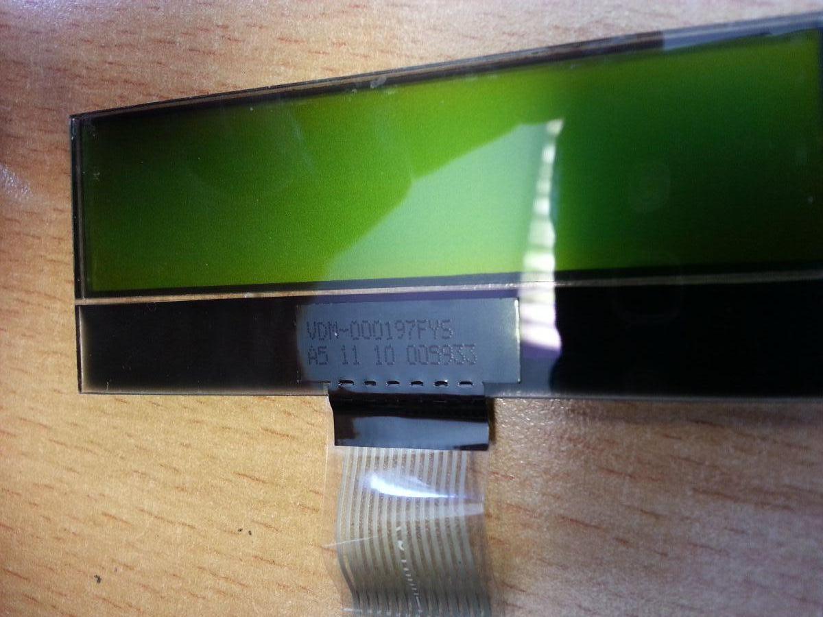
The markings are:
VDM-000197FYS
A5 11 10 005933
-
1
-
-
My Skywatcher HEQ5 came with the older V2 handset and runs Ver 2.05 of the Synscan Firmware - despite this aged version, it functions perfectly albeit without the ability to upgrade the firmware and some of the advantages of the newer V3 (PAE, Backlash Compensation and GPS support).
Beside this the units looks superficially identical and there seems to be little information to compare and consider the under the hood differences. So what follows is a quick side by side comparison, with lots of pictures.
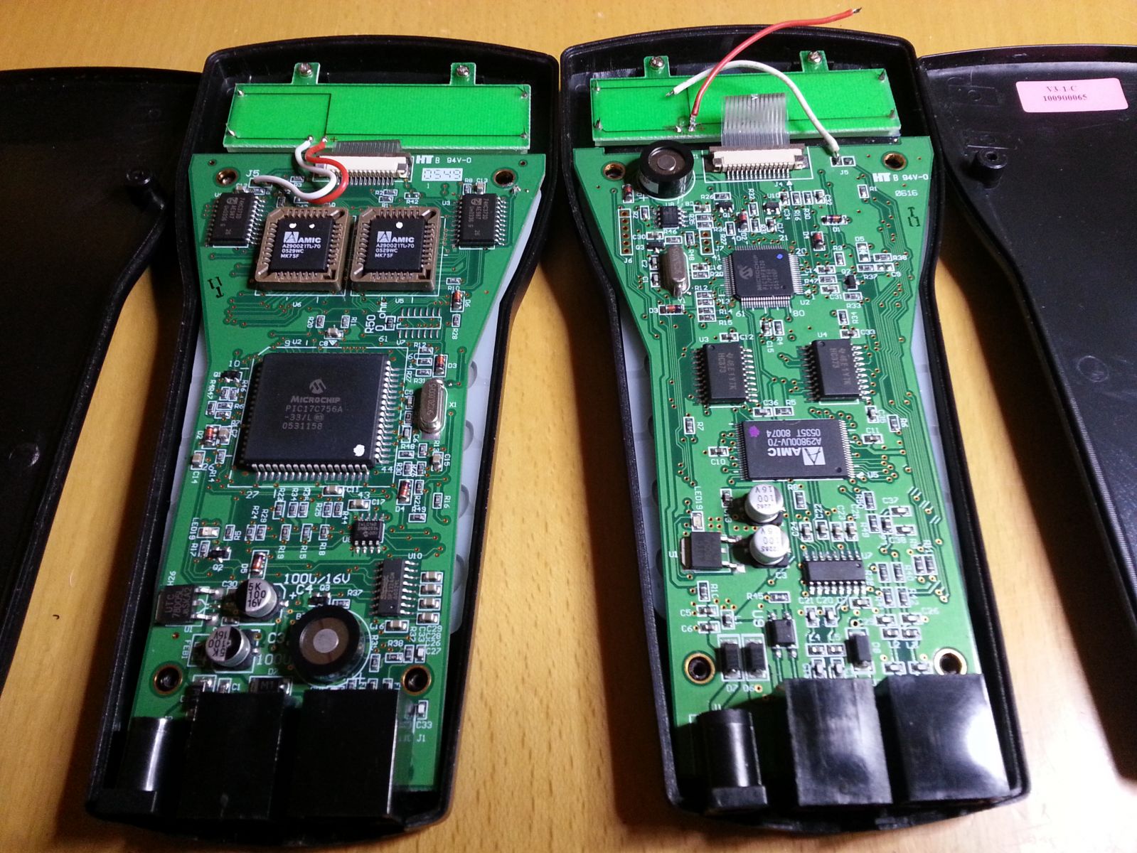
On display are ; left - fully working V2 (ver 2.05) handset and right - a defunct V3 (ver n/k) handset that I'm hoping to resurrect.
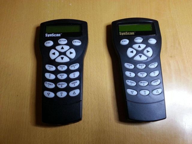
From the front view the units are identical, other than the different coloured Synscan logos, there are no differences between key layouts or connection ports or the backlit LCD displays.
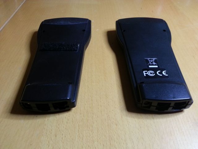
The units are also indentical from the rear view (other than stickers and velcro). There are 4 x No1 recessed cross point screws which are removed to gain access.
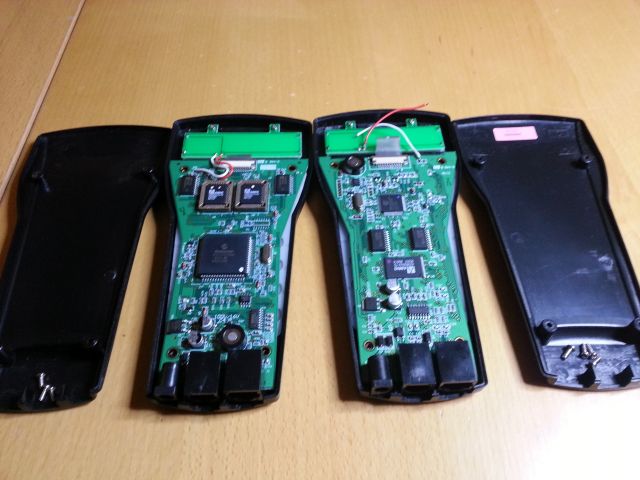
Closer comparison of the two PCBs (Rear View). Here you will notice the changes in layout and updated components on the V3 handset - Although there is commonality of many of the board components, the processor, flash and RAM memory ICs are updated..
Fully exploded view of both Handsets (showing front view/ekypads of PCB): Other than the PCB differences there is full comonality of parts between these handsets.
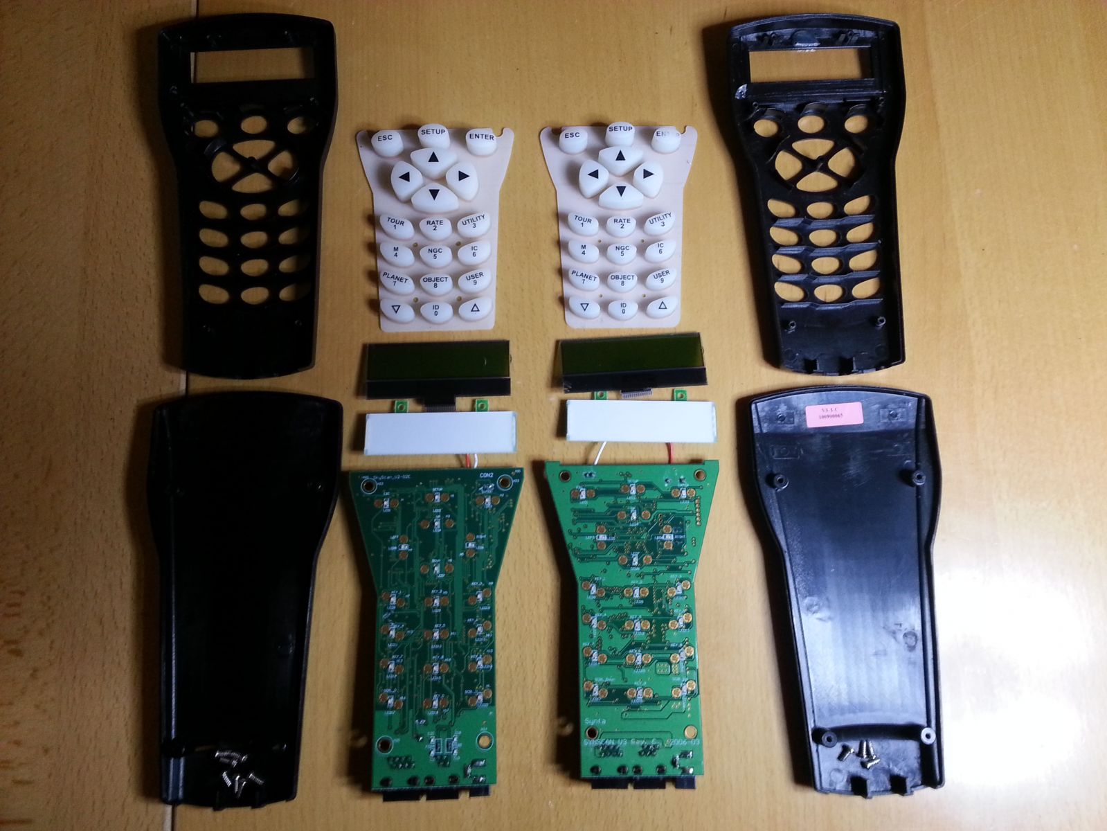
Close up comparison of front PCBs
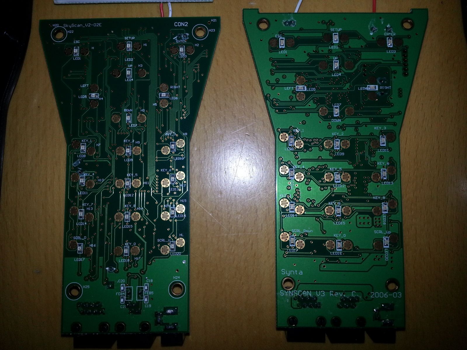
The V3 circuit board design shows significant design simplification corresponding with the layout changes to the rear of the board.
There are some closer images of the PCBs in my gallery
Both units were re-assembled and some minor soldering done to re-attach the LCD backlight on the V3 handset. V2 handset now working with less sticky keypad membrane and the V3 handset is still stubbornly refusing to give any sign of life, though a quick check with my multimeter revealed useful voltages at key points - seems likely that the main logic is dead!
Hope this is of use for future reference

-
3
-
-
How about sash window cord - not so sure on strength, but it is non stretch and should take a fair bit of wear.
-
Obviously the odds are stacked against any of us witnessing the death of Bettelgeuse, but found a great image of the star and its ejected dust rings taken by Herschel on the Register this morning - http://www.theregist...llision_course/

With a mere 5000yrs estimated until the bow shock collides with the dust fillament, it may offer a few visual treats before its final hurrah!
-
Sad news indeed, but such an inspiration to so many of us he will be remembered for a very long time and leaves an amazing legacy to us individually and as a nation. RIP Sir Patrick
-
Black Holes not good - by definition it seems to imply you have to stop posting and perhaps eating random threads in the forum.
Quasar seems rather more productive to me, but perhaps the entitlement bar needs to be set a little higher to represent accumulated mass (10 billion solar masses+)

Short term obsy
in DIY Observatories
Posted
If money was no object then something like this grp dome kit would be nice http://cuckney.pwp.blueyonder.co.uk/astronmy/dome.htm, supplied by Skydomes UK Ltd of bude, who sadly don't appear to be trading any longer. The kits from Pulsar look very nice, but sadly well beyond my meagre budget