


malc-c
-
Posts
7,572 -
Joined
-
Last visited
-
Days Won
1
Content Type
Profiles
Forums
Gallery
Events
Blogs
Posts posted by malc-c
-
-
I find this whole thing really frustrating beginning to wish I had not bothered now and saved up for the HEQ5 mount instead as according to LVI the EQ5 conversion is not going to work with my autoguider and if the speed of my tracking motors at 1x is too slow for all the autoguiders on the market as this guy is telling me then I have just wasted my money time and effort!
Sorry to hear that. Using software such as EQMOD you can set the pulse width from 0.1 to 0.9 which I assume means 0.x sidereal rate. But then that is what's used to control the mount rather than pseudo pressing buttons with the hand controller that cant be set to anything other than sidereal rate ...
Don't know what to suggest other than try and source a second hand EQ5 Synscan unit and use that... or as you say, invest your cash in a secondhand HEQ5 syntrek version
As for the expense, afraid to say that it goes with the territory when developing any modification. My HEQ5 belt mod has set me back a fair bit and that was with the help of another SGL member doing some machining for me.
-
Glad to hear you're having some success...

-
I'm confused (easily done to be honest
) The Orion guider has a nosepiece - 1.25" diameter including filter thread Connectors
The LVI also has a 1.25" nose piece and the ccd doesn't seem 40mm further back in the housing
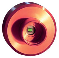
Both also look like a QHY5
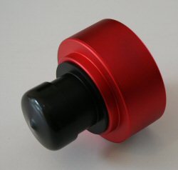
And no eyepiece is used for that, it just bolts onto the end of the finder (OK the nose cone on the QHY5 unscrews) but the focus of the optics fall direct on the CCD. The finder is basically a 162mm focal length (f/3.2) achromatic refractor, so provided the CCD can be placed at or within a range either side of the focal length it should in theory focus ?
-
Dear dear dear... just rang them and the chap was very helpful but the lvi autoguider wont work with it as it wont come to focus.
So much for their statement
The Orion-designed Mini 50mm Guide Scope is a complete and compact guide scope solution designed for use with the Orion StarShoot AutoGuider (sold separately) or similar small-chip CCD autoguider devices.
-
Noo - that's a shame...
But their guider shown in the video doesn't look much different from your camera.
Check out Modern astronomy's website for adapters - I use one to connect a phillips web cam to the SW finder - £29 - a lot cheaper than the £40 you've been quoted http://www.modernastronomy.com/accessories.html
-
Looks good - and not too over priced... If you priced up a SW 9 x 50 finder and bracket from Bern at Modern Astronomy it would only be a fiver less, and you wouldn't get all the fixing hardware that comes with the Orion scope.
To be honest, I might get one for that money and use it on the Mak127 or even substitute it for the ST80
Nice find
-
Chris got there before me - Resistors have no polarity, you can solder them either way round. The transistor however should be connected as shown, with the flat side up
-
Hya Malc ,I'm about to attempt this mod however I'm a little unsure about the connection arrangement for the resistor & transistor to the WHITE TX wire. Are you able to clarify the arrangement ?
Hi,
I take it you are following the build in the 1st page of this thread

Just solder the white wire and the right leg of the transistor as shown
-
More cold weather on the way so the weather man tells me so if you read in the East Anglian daily times about an astronomer being found frozen solid in his back garden it will most likely be me
LOL - I have the luxury of either using the warm room in the observatory, or if it's that cold, can remote into the Observatory PC and do everything from the comfort of the living room, only having to pop out to close the roof up when its time for bed
-
The basis of guiding as I understand it (and I'm still a novice) is that regardless of using an autoguider or PC software the system has to calibrate the mount / camera system. It does this by sending a pulse to the mount based on the settings in the software / firmware and measuring the pixels the star moved. If the settings result in a pulse that doesn't move the mount enough to detect movement then this is why the software reports this as an error. Often it's a case of changing some of the guide parameters in the software or re-running he auto-calibration settings again until it starts guiding.
I'm not familiar with your motors used but on my HEQ5 I can't see the motors moving but the mount does sing as the pulses are applied. I can only assume that as you saw both RA and DEC motors moving and the system told you it was guiding then all must of been well ?
Like I said, I'm still a novice and still learning how to tweak setting in the software and getting decent results... but hope that helps
-
I have a few questions that if you have time to answer would be great :
1. Do many Guide camera's have a st4 port?
2. You talked about being precise, what would this include?
3. I take it the guiding software will adapt to the motor gearing?
Thank you very much for trying the mod, great money saver.
1) - Most of the dedicated astro cameras from the QHY5 upwards have ST4 ports
2) - Not sure in which context this is referring to. Generally it helps to have the polar alignment as precise as possible to minimize tracking errors
3) - the software doesn't know didly squat about the gearing. What you are doing is using software (once calibrated) to measure the drift of a target star captured by the camera. The software then works out how long a pulse is applied to the mounts axis (DEC / RA / or both) to put that star back where it was, and then sends this pulse to the mount. If you have PHD set to On Camera it will use the ST4 port on the camera to communicate this instruction to the mount. Using this conversion the NSEW buttons on the handset receive the correction pulses and thus trigger the response, almost as if you had pressed the buttons momentarily yourself. It then repeats this over and over again, in a basic closed loop - measure deviation - calculate - send pulse(s) - mount moves - back to the beginning
-
The complete material costs came to just under £1850, but the complete build came to £2200, and that included things like the desk, chair, and all labour / equipment hire charges.
-
Thanks Steve,
There are still things I want to do, like line out the scope room with ply, and fit some white lighting in there too, but other than that it's proved to be very functional, and I'm happy with the way it's turned out.
-
Sorry to say the frog is toast !

It wasn't in good shape anyway, especially after the mother-in-law sat on it thinking it was solid and squashed it completely - a classic "you've been framed" moment - just wish I had had the video camera to hand and earned myself £250 !!
-
I agree with Chris. The FTDI cables work really well with the SW mounts. They are a little bit more expensive, but are well supported with drivers and documentation readily available from the web.
-
Beamish, trust me I have every confidence you can do this... If you get stuck I'm sure I have stacks of those transistors laying around in my hobby box and could post a few plus the resistors off to you - just drop me a PM if Maplin let you down...
-
I don't wish to start adding transistors or owt else to it once it arrives cos I don't know what I'm doing- it needs to be a "dummies" version for some of us

I think Dave's pictures are as simple and as clear as it gets, it's only three components, and if you place the transistor as shown, with the legs connected as per the image then it shouldn't be a problem...
-
Dave, thanks for the info. I've just ordered a few to have a play with. Beats the £17 I paid for the last cable. The good news about splitting the case means that wit care it might be possible to fit one or two additional components in the case. I'm looking at using a 4N25 opto isolator directly connected between the PCB and the camera for a serial shutter release for my 400D - I've tested it on the breadboard, now hopefully will be able to produce a neat end product at the end.
With regards to the cable length, traditionally serial cable has longer runs before a repeater is required. Not sure if that applies to these new TTL levels, but if it similar, then extending the cable on the serial side may be better than on the USB side.
One other option is to crimp an RJ plug on the end of the cable and secure with a small amount of glue...assuming the stock cable length these adapters come in is OK for your set up
-
Dave, did you cut open the converter or does it bolt together ?
Also is it 5v TTL or 3.3v ??
I'm in need of making a new canon shutter release, and this might fit the bill
Should of read the post a bit closer

-
Apologies...
-
I did it !
The result, here:
You might like to read through this thread again... I'm sure Chris has stated that if you are using the handset then the tracking rate will be out as the factory gear ration is something quirky like 3.94:1 or something similar. Therefore these mods only work correctly when using EQmod which has been set to match the correct ratio for the pulleys used (4:1 being used for the pulleys on the EQ6 in this thread)
-
Kat, the torque required by a model 4x4 car or helicopter hauling its self to full speed in as little as a few seconds will create more torque than a EQ mount doing its thing.
Gary
Can't comment on the cars that Gary raced (races ?) other than to hurl a couple of kg of RC car from a standing start to 40mph (or more) must put a huge stress on the belts.
Similarly, having 3kg of RC helli going from a stable hover to full pitch climb out puts tremendous amount of torque on them too... As Gary states, the torque required to get 10kg - 20kg of balanced scope moving is negligible by comparison, and may last longer than the brass gears in the lifetime of the mount
-
Kathleen, I think given the final ratio that there would be very little chance of belt slipping.
-
Have to agree with Gary. Most of my RC helicopters were belt driven.. and they never had a belt show any signs of damage
Guiding conversion project for 200p and EQ5
in DIY Astronomer
Posted
I've been gogling around and it would seem that the Smart guider has a fixed pulse of 500mS, which is probably why when calibrating is causing the star to move out of the field of view. Without hacking the firmware I doubt if there is much that can be done.
The SmartguiderII however has variable pre-set pulse durations but even their manual is confusing. The table states 25, 50, 100, 250 and 500 mS but the text below this describing the menu option states allowed values are 30, 60, 125, 250 and 500 ms ????