


12dstring
-
Posts
111 -
Joined
-
Last visited
Content Type
Profiles
Forums
Gallery
Events
Blogs
Posts posted by 12dstring
-
-
This is the result of this weekend's work. I'll need to make up a smaller tool to scrape near the edges, already had one close call with the gold wires (ok, I don't need to go right to the edges.. but it's nice to do things properly).
All looks fine so far, no issues with the flat fields as with the polishing method. Once I'm finished it'll need a good clean up to remove all of the filter debris though.

-
 5
5
-
-
It's just the white balance. You'll see in the top right, where the bayer filter is still there that one in four pixels is much darker, this is the blue one (darker due to sensitivity and the spectrum of light in the room).
When it comes to converting the raw image to colour it will boost the blue pixels to balance the colour. Where the bayer filter has been removed, all pixels will be equal in brightness, but during the colour conversion it still thinks one of them has been filtered blue, and boosts the blue accordingly.
-
I've started on 350D sensor #2, after practicing with the first one. I've swapped the metal dental pick for a scraping tool carved from the plastic end of a paintbrush. The plastic won't scratch through the layer beneath the filter like the metal can do, but does an adequate job of scraping off the filter.
The first pic is a flat(ish) field. The darker area is the top layer removed, you can see again that sensitivity takes quite a hit with the loss of the microlenses. The blueish area is with the filter layer removed.
The second is a crop of some text. The original with bayer filter on the right, filter removed on the left, and just microlenses removed on the strip between them.
The raw image on the top, and then demosaiced on the bottom.


-
1
-
-
I just had a thought to help out the sensitivity of the stock colour canon 1000d sensor. And thats just to remove the glass/plastic cover on the sensor. From looking at ccd tests with the class removed you get about 5% more light, its easy so i might do it to my one if it ever gets a chance to get used again.
I was pondering whether to put the glass cover back on. Any bit of glass is going to lose you around 5%, and having no glass in the image train at all would be good for Venus images as you'd get more UV reaching the sensor. I suppose the shutter will be closed when the camera is off the telescope so the sensor will be fairly protected without the glass.
Not a DSLR I know, but here's some interim test results with an SPC900NC.
In between the original section and where the filter's been removed you can see a dark patch where just the top microlens layer has gone. You can see it decreases the sensitivity a fair bit, but this is then made up when removing the filter. The net result isn't a huge change in sensitivity in optical, but it'll be noticably improved for IR and UV imaging. However the improvement in resolution is pretty obvious even with my crude test-card setup.


-
2
-
-
I think this sensor has had it
 I'm having no luck reattaching the gold wires.
Apart from that the actual filter removal is going well. I think the potential advantages are worth having a go with another sensor, so I'll open a new one up tomorrow (with extra care this time).
More 350Ds than sense...
-
Just had a go with an ICX098BQ from an SPC900NC, I couldn't tell the difference between them, the layers seem almost identical and are removed as easily by scraping (no solvents).
Didn't even think it had microlenses


-
1
-
-
I've got it under a microscope now, definitely two of the gold wires no longer connected due to the broken glass, so will attempt to reconnect with some silver glue at some point and try and bring it back to life.
In the meantime I've been plating with surgically removing the bayer filter. I tried a few solvents; IPA, acetone and xylene had no effect at all. I don't think this is the way to go here in any case.
I did some probing with the rounded edge of a dental pick. There's several distinct layers, the top one is the microlenses (visible on the left in the image below). This is very soft and easily removed by just brushing the pick along the surface, it almost feels gel-like at this scale.
With that gone you can see the darker filter array underneath (upper centre in the image). This filter layer feels glass-like, and it doesn't take much force to break a hole in the surface, and once you've done that it's easy to remove more as the edge crumbles away quite easily with further force.
Once this is removed you can see the yellowish photosites underneath. They seems to be covered by a glassy substance (planerizing layer?), it's very smooth and isn't easily damaged - though can be scratched with the sharp edge of the pick.
My feeling is that polishing will have the problem that you won't know how far you've gone through the filter array, or if you've started polishing away the layer underneath (causing the uneven flat fields?). I'll keep scraping away the filter under a microscope. Sure it'll take ages, but I can easily see what I'm doing and if I damage anything, and can be much more precise around the edges. If the filter removal goes ok but can't bring this sensor back to life, I could probably persuade myself to try on another one. I'm pretty confident I can remove the cover glass in one piece if I tried again, and for a backup would put tape over the glass first in case it breaks.
For reference the image below is around 320 microns across, or ~1/70th of the sensor width

-
1
-
-
Good luck
 I suggest testing the sensor after removing the glass but before going any further.
Thanks Gina, and testing first was a good idea.
I popped it back in and got the dreaded err 99 after taking a picture. This didn't happen with the sensor unplugged (which I know just gives a black image, but no errors).
Taking the sensor out and inspecting closely I think one (maybe two) of the gold wires aren't quite connected any longer.
I'll check with the microscope next week. It's not the end though, I've soldered smaller things...
-
This looks like fun

I have a water damaged 350D I bought a while back for spares, the main board is toast but the sensor worked fine... so it's now volunteered itself to science.
The cover glass didn't want to come off nicely in one piece, but got it all of eventually whilst holding it upside to avoid any tiny bits of glass falling on the sensor.
I'll have a play with it under a microscope next week, and see if any solvents have any effect before attempting to polish it off.

-
That setup will allow you to autoguide the mount, but you won't have any GOTO capabilities. Those motors are only for tracking and slow movements.
You'll need the Synscan motor upgrade kit if you want to use EQMOD and be able to point the telescope with a computer.
-
Have you got a link to the motor upgrade? If it's the same as the Synscan kit but without the hand controller then you should be fine.
-
That modification only adds autoguiding capabilities.
To work with EQMOD you'll first need the Synscan upgrade: First Light Optics - SynScan PRO GOTO Version 3 Upgrade Kit for EQ5
-
PL-2303 drivers are found here: Welcome to Prolific
-
To follow the pictures you'll need:
1 x 2N3904 transistor (although really any of Maplin's "Low Power LF NPN Transistors TO92 Case" will do)
2 x 10k resistors - 1/4W size (or Metal Film 0.6W from Maplin's are the same size)
The mosfet circuit doesn't have any advantages over the transistor one other than only needing 1 resistor, but I suspect people would be more likely to have NPN transistors lying around.
-
I've not had any problems with mine, however unmodified it will be more susceptible to noise so if you have a noisy power supply or nearby cables for example you'd be less immune to that noise and communication errors would be more likely.
If you've got a soldering iron then I'd recommend the mod even if it works without, as it's pretty simple and allows you to extend the cable if needed (10m as Glider says). It just pushes it over the £4 mark.. but only by a few pennies

-
Recommended mod to bring the signal output up to 5v
Either of these circuits will do, to help with noise immunity and longer cable lengths.

My implementation:

Top

And fitted back in the case:

-
1
-
-
It's a sound point.
The simplest method is probably the mosfet+2 resistors as shown here: Bi-Directional Level Shifter – HUSSTECH
The 2N7000 is a TO-92 part so should fit in the case snugly, and the two unconnected pads along the bottom next to Tx are 3.3v and 5v if I remember correctly so should be easy to tap into them.
I've only got surface mount mosfets at the moment, which I know isn't everyone's cup of tea, so I've ordered a few 2N7000s and will post back with pictures when they arrive.
Another way to help with any noise issues is to shorten the cable, and extend if needed on the USB side. If you need more than 5 metres then probably best to stick with the RS232 version.
-
I originally planned to have a little 3.3v-5v level shifter circuit as well, but I left it out after I tried without and it worked. I've had mine running over the past month with no issues.
I'll open up my mount tomorrow and check the specs for the PIC, if it would prefer more than 3.3v then there's enough room inside the converter to add a few components to bump up the output to 5v.
-
I know I've been quiet for a while, finishing my degree and now living the dream working as an observatory technician now. It's no excuse for not posting more though...
I was aiming for a neat all-USB approach for my setup. One USB cable to my SPC900NC guider, and my DSLR is going to be modified to include a USB hub with an 'auxilary port' on the side of the camera box. The EQDir can then plug into the camera and I'll only need 2 USB cables going between the camera and mount (plus power).
The converter casing can be pulled apart with the aid of a thin flatheaded screwdriver, and can be pushed securely back together again.Dave, did you cut open the converter or does it bolt together ?Also is it 5v TTL or 3.3v ??
I'm in need of making a new canon shutter release, and this might fit the bill
To clarify, the chip in the converter is a 3.3v part, but the Rx input is 5v tolerant (so no problems talking to the mount). All the outputs from the converter will be at 3.3v. I'm planning to use one for my Canon DSLR shutter control using NPN mosfets (which trigger at 1.5v), but the normal transistors will work just fine.
Edit: The chip is a PL-2303HX (rev. A). Here's the datasheet if you want more details: http://www.prolific.com.tw/support/files/%5CIO%20Cable%5CPL-2303HX%5CDocuments%5CDatasheet%5Cds_pl2303HX_v1.6.pdf
Edit 2: No problems running Win7 64 bit
-
Take one PL-2303 USB-serial cable (e.g. USB to UART (TTL) Cable module PL2303 Converter | eBay) - £2.99
One 2m RJ45 ethernet cable (e.g. 2m BLACK RJ45 CAT5 PATCH ETHERNET NETWORK CABLE LEAD | eBay) - £0.99

Remove one end of the ethernet cable and strip back, check wiring colours.

The USB serial converter has a small circuit inside:

As a side note, the little PCBs are great for mods that need a serial interface such as webcam long exposure mods or DSLR shutter cables. The DTR and RTS signals required for them are indicated below (labeled A and B on the PCB). Note the chip is a 3.3v part with 5v tolerant inputs, so make sure you choose a part to interface it with which as Ok with 3.3v level signals (i.e. 74LS00 for the SC1 mod). Ideal for compact USB-only mods as done by yesyes ( http://stargazerslounge.com/diy-astronomer/148315-spc900-lxmod-yesyes-style.html), the chip is the same type, but the PCB smaller as it doesn't have the RS232 voltage level converter meaning you can interface directly with logic levels parts instead of needing diodes+transistors.
(You don't need to worry about RTS and DTR for the EQDir.)

Connect the two cables as follows:
Gnd-Gnd
Rx-Tx
Tx-Rx
If your connector wiring colours are exactly the same as in these pictures, then the connections are as follows:
Black - Orange/white + Solid blue
Green - Blue/white
White - Solid green
Pair the unused solid brown + brown/white off together (12v)and insulate them from the others. Same with the solid orange and green/white.
Do check with a multimeter before hand to make sure you have the 12v lines correctly identified.

Make sure all lines are nicely insulated and give it a test, and add some heatshrink when done.

Worked first time on my XP laptop. Will try on Windows 7 64 bit later.
Total cable length is a little under 3m, can be extended 5m on the USB side.
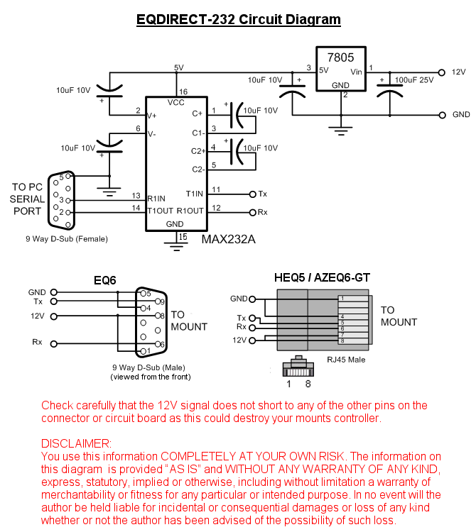
This is for the HEQ5, for the EQ6 just swap the RJ45 ethernet side with an RS232 DB9 cable and use the EQ6 pinout here: http://eq-mod.sourceforge.net/eqdirect_232.png
-
3
-
 1
1
-
-
Anyone managed to remove the cable from the housing yet without breaking the housing? It looks like the connector to the camera board was added after the cable was threaded through the housing.
After unplugging from the board, grip the cable from the inside where it comes through the housing with some pliers (there's two notches on either side) and turn it 90 degrees. You can then pull it out easily.
Dave


Debayering a DSLR's Bayer matrix.
in DIY Astronomer
Posted
Here's a flat, f/8, heavily stretched to bring out the lovely details.
This is only after brushing off the loose debris from the filter removal. Once I've done the edges I'll clean it up properly with IPA and compressed air and post another.