


drjolo
-
Posts
493 -
Joined
-
Last visited
-
Days Won
1
Content Type
Profiles
Forums
Gallery
Events
Blogs
Posts posted by drjolo
-
-
2 hours ago, Bajastro said:
But I have similar problem as @drjolo . Image of star in my guider module is very low quality.
I have checked yesterday my guiding lense - it was tilted about 1mm (!!) in the holder. The guiding lense holder has very small holding ring (0.2mm), and setting lens position precisely is not an easy task. I redesigned it a little, so holding ring width is now about 1mm. The lens aperture is then little bit lower, so the image may be little bit darker, but also better quality. This lens focal ratio is f/2.4, so it is extreme especially for simple doublet lens. Fraction degree tilt may degrade image significantly.
With this new holder I adjusted and checked all using 25um artificial star. Results are promising, of course reflections are still there, but the star image quality was good, and once placed at the slit it almost disappeared - so most of the light was focused well. Now I need to wait for another clear night for real tests.
-
If you align spectroscope slit along E-W direction, then tracking and guiding errors will move star along slit. You will not loose light then when star moves off the slit, only the spectrum will be little bit higher.
-
Two days ago I collected night sky spectrum as well, but this time without clouds and without Moon. I estimated NELM to 4.5mag - some haze and high clouds were still present.

Hydrogen absorption lines that came from sun light disappeared due to missing Moon. Oxygen glow at 5577A is much more visible. Also I adjusted focus much better, so now Na doublet at 6154A is resolved, and also some peak appeared inside wide Na absorption line at 5890A that comes from high pressure sodium lamps. Small peak around 4500A probably comes from blue part of white LED light https://www.nature.com/articles/lsa2015105/figures/5 .
-
 4
4
-
-
Ken, thank you for your suggestions. I will review guider path and check guiding mirror and lens once more. I have 25um artificial star that should help to figure this problem out.
Despite such poor guiding image PHD did a good job and RMS tracking error was about 0.6" total in both axes. And here is my first star spectrum, calibrated with Relco starter and processed in BASSProject software.
I am very happy about it
") Resolution is quite good, both Na doublet and Mg triplet were separated.
Resolution is quite good, both Na doublet and Mg triplet were separated.
-
5
-
-
Today some stars appeared at my night sky, so I attached spectroscope to the 10" Meade ACF f/10 telescope and made first light. I was able to obtain first spectra of bright stars, however I am a little bit concerned about the shape of the stars image at the reflective slit. I have slit mounted with reflective surface pointing to the camera. The star (Betelgeuse) image looks like this:
These 6 images shows star at different focus positions. Telescope is collimated well, because I checked it before I put spectroscope into the focuser. The resulting spectra is extended vertically (along the slit) and also slanted in different directions at different wavelength:
Left image is blue part of the spectrum, right image is red part. This spectrum was done at the focuser position that corresponds to the third image from left in the upper row of focusing images.
I wonder if I should reverse the reflecting slit, so its reflective surface points to the telescope.
-
3
-
-
I was not yet able to point my LowSpec spectroscope to stars, but Saturday evening I pointed it to the cloudy night sky to measure and identify main light pollution sources. LowSpec has 600 l/mm grating, and camera used was QHY163M.
Main source of LP at my location are high pressure sodium lamps, that are responsible for emission Na 5688A and wide bell shaped 5890A line with absorption peak. There are also few weaker lines that comes from mercury Hg - these are emitted by different type of street or garden lamps. Natural airglow that comes from oxygen occurs at 5577A and 6300A. First of these lines can be identified, however I was not able to detect anything meaningful at 6300A.
There are also two obvious absorption lines at 4861A and 6563A - I quickly identified them as hydrogen beta and alpha. But I had not idea what could be the source of such lines in the spectrum of night sky background. After some time I remembered that night before I admired almost full Moon in the sky. And Moon reflects Sun light, so these two lines comes probably from Sun light reflected from Moon and then dispersed in the cloudy night sky. Barely visible magnesium triplet confirms this. However I plan to take night sky spectrum two more times when Moon will not be visible - with and without clouds.
-
8
-
-
1 hour ago, Thalestris24 said:
I'm wondering how you manage if you can't avoid having more than one star on the slit? I suppose you have to just go to a different star...
In this case I think you will just have two spectra that you can process separately. You may select both stars regions and analyze separately.
Today I designed and printed simple Relco SC480 starter holder to LowSpec - I attached the models and the source file. It requires to drill 12mm diameter hole in the LowSpec cover - in the optical axis, near to telescope inlet. Then holding element needs to be glued into this hole ( I used superglue ). The limiting resistor for starter is placed in the AC plug. Here are some photos:
Starter can be put into LowSpec and secured with nut. Then after calibration it should be removed, there is another nut to cover the hole, and also safety enclosure for starter. I tested calibrating of Sun spectrum using SC480 in this holder, and I was able to measure Sun spectral lines positions with 0.15nm accuracy (600 l/mm grating, about 0.4nm FWHM). This starter should also help to focus main camera, when real target is very faint.
Sun spectrum calibrated with SC480 starter in BASSProject software:
Relco SC480 starter spectrum:
3D models to print and source file (SCAD). It should be printed with layer height 0.12-0.15mm: relco-starter-holder.zip
-
4
-
-
When I measured FWHM of different lines it also gave me some different results - for orange/red part I got R values from 1300 to almost 1700. You may double check if spectrum image is focused well, because it definitely affects FWHM.
-
1
-
-
16 hours ago, Merlin66 said:
Have you measured a line FWHM and determined your R value?
Today I mounted Relco SC480 starter to my LowSpec and after careful collimation I checked its resolution. I also installed BASS project software - works like a charm.
According to SimSpec excel sheet I calculated resolution of LowSpec with 600 l/mm grating to about 800 at blue and about 1100 at red (I used 25um for lenses resolution). Real measurements with Relco starter indicates higher resolution - about 1400-1600 at red and about 1100-1300 in blue. However this test was performed without any optics - I just put starter in the front of 30um slit.
-
Thanks Ken! I used 30um slit - this will be the slit at my observatory telescope (Meade ACF 10" f/10). I have not yet measured R, I will do it after final collimation (actually I forgot that R is determined from FWHM
 )
)
Thank for pointing out BASS project - I will be happy to check another software. Last days Vspec made me little bit nervous.
-
Hi again!
Yesterday evening I assembled LowSpec device - I still miss focusing bolt, so I need to focus manually moving the camera. And also spectroscope collimation is rough, for testing purpose. But first results are very promising. I have used all standard optics from LowSpec and 600 l/mm EO grating.
I used Altair IMX224 camera.
First test frame with workshop fluorescent lamp:
Mosaic of full visual range:
And plot from Vspec:
Today morning I recorded few Sun spectra. Doublet Na:
and magnesium triplet:
I am pretty happy with this test results. I think after careful collimation and mounting focusing bolt resolution will improve a bit.
Many thanks to Paul for this outstanding project and to Ken for constant support!
-
5
-
-
Together with one of my colleagues we also assembly two LowSpecs. I am working on medium resolution version with 600lpmm grating, and my friend ( http://www.jgao.pl/ ) is doing low resolution version for supernova program. We already have all elements 3D printed (all fits perfectly, great design) and almost all mechanical and optical parts ready. We have used entry level Ender 3 printers and Impact PLA filament. Impact PLA is PLA family filament, but more like ABS durable and more heat resistant - regular PLA can become soft at 50*C already.
We have little doubts about reflective OVIO slit orientation. In original PDF manual the slit has its front (metal plated) side directed towards the grating. But then one of users noticed that guiding is somehow degraded, so he decided to place OVIO disc oriented with front towards guiding camera (like in my image to the right). But then I suspect it may affect the spectrum quality, because light after passing the slit still needs to travel through OVIO disc glass.
What is the correct orientation of reflective OVIO disc?
-
2
-
-
Thank you for hints, I will try it out. Meantime I found a way to do it with MaxIm DL (as long as you have MaxIm
) . Here is corresponding piece of vbs script:
' Declare variables.
Dim myDoc
Dim fileFormat
Dim filePath

'Initialize variables used in call to SaveFile method.
fileFormat = 3 'FITS

' Create a document object.
Set myDoc = WScript.CreateObject("MaxIm.Document")
filePath = "C:\path\to\file\"
myDoc.OpenFile filePath & "Sh2-135_60sec_filter1__0005.fit"

' Crop file Document.Crop (XOffset, YOffset, Width, Height )
myDoc.Crop 3600, 80, 500, 500

' Save result to disk under a new name.
myDoc.SaveFile filePath & "Sh2-135_60sec_filter1__0005_crop2.fit", fileFormat, false, 1

myDoc.Close
-
SGPro does not offer subframing for its sequences, and that would be very useful for variable star observing, so I will not end up with 60GB of data after one observing night (16Mpx camera). So I figured out I will write a script that will be invoked after each target end and will crop FITS files from selected folder. Do you know any windows command line tool that I could use to crop FITS file and preserve FITS headers? I tried with ImageMagick, it crops quick and fine, but also deletes FTIS header entries
-
Thanks Bryan. I think that's true for SCT telescopes - they are more popular among planetary imagers and spectroscopy amateurs than for DS imaging.
-
Cygnus Wall is well known fragment of NGC7000 North America nebula complex, that is also a part of even larger molecular cloud. Maybe not everyone knows, that the star responsible for ionisation of NGC7000 cloud was not known for a long time. Recent studies indicates, that it may be star denominated 2MASS J205551.25+435224.6. This is hot O-type star obscured with clouds of dark matter, and invisible to visual observations.
Image below was captured at my backyard observatory with Meade ACF 10" telescope on EQ6 mount and QHY163M camera with Baader filters. It is composite of Ha 200x2 minutes, Oiii 75x2 minutes and RGB 50:40:40 x 30 seconds. Data was captured during three nights 28-31 of August. Seeing was mostly good, transparency average-good, suburban sky.
Cygnus Wall fragment in hydrogen alpha band
Cygnus Wall fragment, HORGB composition
-
16
-
-
Thanks Wim, this year it was 4 hours of Ha and 3 hours of Oiii. So the amount of data for Ha is similar to last year, but I suspect the Moon light swallowed outer shells even in Ha band. These outer halo is really faint, I think at my location it requires about 10 hours of Ha exposure without Moon to achieve good result.
-
1
-
-
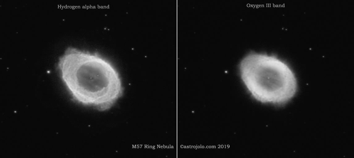
I got back to M57 one year later - this time with narrowband data only. Seeing was decent, but transparency was far from perfect and also Moon was present. So outer halo has not been captured.
Anyway, here it is M57 in narrowband bicolor only:
And both narrowband channels
Meade ACF 10", CCDT67, QHY163M, EQ6, Ha 120x2 minutes, Oiii 90x2 minutes (gain 100), seeing good, transparency moderate, Moon present.
-
4
-
-
On 11/02/2019 at 22:32, matt_baker said:
Just out of curiosity, what was the exposure time for the Crab and Eagle nebula's. Also, they're fantastic!
Thanks
It was Ha 55x5, Oiii 25x5, RGB 18:12:12x1 minutes for Crab, and Ha 115 minutes in 5 and 2 minute subs for Eagle.
-
Definitely you need to power stick with regulated voltage. 12V battery with DC converter to 5V is good idea, for powerbank - I do not know if you can draw constantly 2-2.5A, maybe yes. If yes, then it would be more convenient, because you do not need to use DC converter. But power bank contains usually 3.7V battery and boost converter to 5V, so the max current is limited by output converter.
-
1
-
-
In some extent it depends on the USB ports the stick is equipped with. I have measured power consumption of several sticks and mini PC, and the rated power is usually a sum of stick own power requirements plus USB ports. USB2.0 port should be able to provide 0.5A, and USB3.0 1A (but of course not all USB components will drain that much power from USB port).
So now is all up to what you plan to connect to your USB ports. If all USB ports will be loaded with maximum allowed power, then you need as much current as it is stated. Otherwise stick itself requires about 1.5A (at 5V) maximum when CPU is 100% load.
-
1
-
-
It is always a hard decision - it somehow depends on your sky quality. If your imaging location provides visible Milky Way and NELM at level 5-5.5mag or better, then OSC camera will do the trick. But if LP is worse, then you probably achieve better results using mono camera with LRGB and narrowband filters. This is my case, I have NELM limited to 5mag during good nights, sometimes it reaches 5.5mag. I have tried with OSC cameras and DSLR few times already, and always got back to mono. However I was pretty happy with having for some time both QHY163M and QHY163C cameras. I used mono for luminance, OSC for colour and it worked pretty well (like here for example https://astrojolo.com/astrophotography/galaxies/m106-after-four-years/ ).
I also wrote a post about it at my blog https://astrojolo.com/gears/colour-camera-versus-mono-price-of-comfort/ - at the end you may see sensitivity comparison between OSC and mono cameras.
-
Congratulations on your captures! Here is my five picks:
Heart and Soul and comet (with Samyang 135 and QHY163M):

Four next were made with Meade ACF 10" and QHY163M.


-
20
-
-
Thanks! Yes, I plan to add colour to at least some of them. And also more luminance to Abell 1185


The Lowspec spectrometer
in DIY Astronomer
Posted
The lens fit perfectly into the holder inner diameter, so this dimension is okay. But (at least in my case) this protruding edge was too thin, and was not able to stop lens in the stable position. Lens fits tight to the 12.75mm hole, but it tilts and wobbles at this thin edge. I made this edge a little bit larger, so the aperture is now 11mm, printed it with 0.12mm layer height and it seems to be much more stable now.