


badgerchap
-
Posts
1,604 -
Joined
-
Last visited
-
Days Won
3
Content Type
Profiles
Forums
Gallery
Events
Blogs
Posts posted by badgerchap
-
-
This ol' thread still going eh? Nice work QM

-
Well what you have so far must be fairly sufficient so not worth the fish for a few pixels' worth of sensor area
Typed inexpertly from my phone
-
 1
1
-
-
That must be a fairly use able area there, plenty bigger than many CCDs I imagine. Are the speckles remaining bits of CFA or dust or....?
Typed inexpertly from my phone
-
I feel I'm getting to know your back garden pretty well after this thread!

-
2
-
-
Love seeing so much time and effort expended into what is, effectively, undoing someone's very hard work at the Canon R&D dept
Looking forward to those darks Also looking forward to your efforts with the 450D - by the sounds of things, that might be an easier project for me to emulate! -
Thought I'd just mention that I have finished writing up my own successful debayering attempt on the 1100D sensor - link here - http://stargazerslou...-filter-array/
Mostly copied from here but with a few extra bits added to improve readability - explain things that were covered in other posts here.
Cheers Gina, you're an angel. Now for some reading.....
-
1
-
-
Starting to look pretty snazzy there Gina, excellent work. If you manage to get all the way with this, would you be kind enough to condense your efforts into a shorter thread, like you did with your excellent cooling work? Not that I'm lazy or owt but this un is a bit beefy now!
Typed inexpertly from my phone
-
Well this thread has been running for a while! Interesting stuff though
-
Definitely. Should be cheaper than a new box and won't need to be torn open either! Plus because most of the technical wrangling would be on the computer, there'd be a lot less room for bad connections, dodgy components etc. The only hindrance I can see is that it will be even more vulnerable to dew and damp. Having said that, a plastic bag and a load of gaffer tape could sort that out lol.
-
Looking at the very first entry when searching for "Arduino Stepper Motor Control" on a well known search engine, it doesn't look too challenging. A little bit of fiddling and a small amount of easy-to-acquire hardware (some of which I already have I think). I may well give this a whirl.
-
OO Arduino, I'd not given thought to that. I've seen a number of designs for Arduino stepper motor controllers online, so I suppose you could dispense with the handset entirely. Good thinking James. I'm off to investigate.
-
It seems odd that the microcontroller should be so cheap (I think Farnell sell them singly for about £2.50) yet the programmer seems to be hard to source. Perhaps that's why they're so cheap
I wonder if there's a pin-compatible replacement that does have an easily-obtained reader/programmer that might also read the existing microcontroller, assuming of course that the latter is even possible at all?
James
It may be moderately easy to completely redesign and rebuild these, or come up with some hardware that would allow the job to be done by a PC. Unfortunately, I don't have the skills for this just yet, but am learning. I'm amazed no-one has looked more into these ideas in the past. I'd be gobsmacked if there was only a single chip that could do this job.
-
Isn't it about time sky watcher improved this weakness in an otherwise great range of telescopes and products?
I agree. However, I have noticed that since the release of the EQ6-GT and EQ8 that the prices of 2nd hand HEQ5s seem to be dropping slowly. Having seen a 2nd hand one on ABS yesterday for £375, It's hard to countenance buying a new EQ5 with dual axis for roughly that price. It just sucks if you already have the kit I suppose.
I did look at buying the chips and building a copy, but hit a similar problem to Oily - no info on reader/programmer

-
Yes, it would help if there were spare handsets available, or if they were a little better engineered to start with. I guess it wouldn't be hard to solder a 6V regulator across the wires in the box oneself given the skill with a soldering iron. I don't know if a simple bridge rectifier might also be incorporated to protect against reversed-polarity connections -- it's not something I've thought of before.
James
Reversed polarity hasn't given me a problem so far. My adaptation has a removable terminal which routinely falls out and so in the dark I often get the polarity wrong. Never caused an issue, save for temporary inactivity.
Agreed though, initial manufacturing should be better at the price. I'm rather surprised no one in the UK has made a cheaper alternative.
Typed inexpertly from my phone
-
I thought so too, but in the light of Mark's comments in this thread I assumed I must have been mistaken. I'm sure there was someone who had a guided EQ5 who eventually caved in and bought a HEQ5 in the last year or so though.
James
Well with regards to Quatermass' and my own issues, and those of others, I think you have to be a bit masochistic to persist with the EQ5! I know the move upwards is costly, but then when handsets are £100 a go.....
Typed inexpertly from my phone
-
Quarter mass I thought you ended up getting an HEQ5?
I was lucky enough to be permanently loaned an NEQ6, but I still use the EQ5 for wide field stuff. Funny thing is that now it's not my main mount, it's been behaving itself wonderfully. Typical!
Typed inexpertly from my phone
-
Good to know, FLO, and the part about your service certainly holds true for me. Always had a great and quick response, and it's always appreciated!
Posted via Tapatalk on an ageing iPhone so please excuse any erroneous spellings or accidental profanities!
-
I have on occasion thought that it might not be that hard to unsolder the leads from the power connector and insert a voltage regulator between the two. I think the ST4 conversion kit uses opto-isolators, so in combination that seems like a reasonable level of protection given that a number of people have complained about handset failures after similar conversions.
James
It's a little disappointing they don't come with regulators already built in. It'd hardly be asking a lot considering the unit retails for nearly £100 and the most expensive component (the IC) can be bought for less than than £2 for 1!
-
This happened to me (hence this was my second mod this year!) so I know how frustrating this is. The only thing I can say is to be sure your power supply delivers a steady 6v. A decent power supply should be regulated, but in the case of cheaper supplies you may get fluctuations in supply voltage which might cause a burn out. Of course you could solve the whole problem by buying an EQ5 goto upgrade. This has a wider tolerance of input values (11-15v) and obviously already has an ST-4 port, on top of the goto. Shame it costs £300!
-
1
-
-
Glad to hear it went well Oily
-
For the second time this year, I have found myself modifying the motor drive handset from my EQ5 mount, so this time I thought I'd share the process in the hope that it might help someone in their own endeavours. Also, it shows someone thinking of the project just how simple it really is! This post was initially written for my blog, so please forgive me whereever I seem a little patronising. I don't intend to try to teach anyone how to suck eggs! However, there are a number of pictures on the blog which may offer a more complete explanation of the process.
You will need:
- A small Phillips (cross-head) screwdriver - preferably a few millimeters will do.
- A soldering iron,
- Solder,
- Either the 'ST-4 Conversion Kit' which can be purchased from Opticstar (in the U.K.) or Shoestring Astronomy (in the U.S.). Alternatively, you can by any 6 core wire with an RJ12 connector - more on that shortly.
- An EQ4 / 5 Dual Axis motor control handset.
- Either an ASCOM compatible guide camera with ST-4 port or any other suitable guidecam / webcam and a GPUSB* guideport interface, also available from the above suppliers.
- Autoguiding software. I use PHD, which is free, but there are others available.
- About an hour of spare time.
*Please note: The GPUSB interface is only necessary if your camera does not have an ST-4 port. In cases of cameras with this socket, for example the QHY5, the camera itself acts as the interface between the guiding software and the handset.
This guide concerns the dual axis handset that we use to track the sky as the earth rotates. This is fine for your first foray into astrophotography, but due to a number of factors it will not allow you to take exposures much longer than a minute.
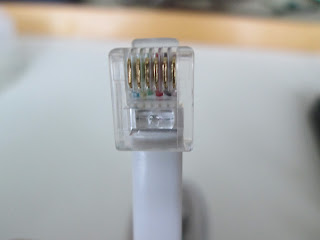
The ST-4 cable: if you're ordering from one of the suppliers above, this will indeed be called an ST-4 cable. However, if you wish, as I did, to purchase one of these from any other (non-astronomy) supplier, it may go by a different name. It will then be known as an RJ12 6P6C cable, the 6 referring to the 6 wires running through it. Be careful not to confuse this with the RJ11 which has only 4wires, and some others have only 2.
Be sure to check that your cables either use the same configuration as used here (White - Brown - Red - Green - Yellow - Blue from left to right with the release clip of the connector facing towards you), or that you can familiarise yourself with the configuration of your cable in order to match the correct cables to the correct soldering joints. Incorrect wiring could lead to damage of your equipment.

Whilst we're on the subject I must point out that this modification is in no way recommended by myself or any of the suppliers of manufacturers involved - you undertake this at your own risk, and any warranties will be invalid.
Right, with the warnings done and tossed hastily to the side, provided you have all you need, it's time to begin!
STEP 1: Remove the buttons
Gently prise off the four buttons with a screwdriver. Use 2 screwdrivers if possible to avoid breaking the buttons. Lay the buttons to one side.
Step 2: Removing the top cover:
Unscrew the four screws at each corner of the handset...
...and the two screws which attach the power socket to the main box.
Then, the handset cover should come cleanly off.
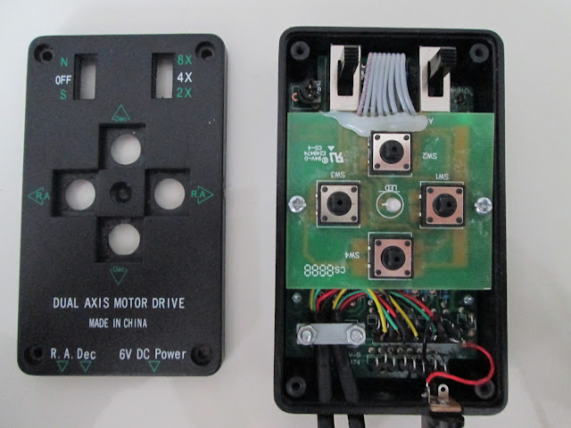
Don't be afraid of what you see if you're unfamiliar with electronics - you can ignore 99% of everything that's in here. Just be careful not to touch anything you don't have to - particularly the chip on the lower board (which you'll see in a moment).
Step 3: Open up some access.
Loosen and remove the two screws that fix the top board to the bottom board.
The top board now lifts away revealing the bottom board, which is the part that the hand controller uses to communicate with the mount. Note the large chip which I mentioned earlier. Be careful to have as little contact with this board as possible.
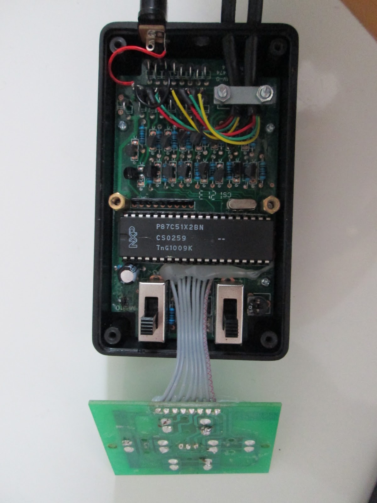
There are three small screws holding the bottom board in place - remove these also.
Step 4: The Cable grip.
Now the cable grip - we will need to remove this in order to lay our new cable underneath it after soldering. It is most convenient to undo this grip now, so as not to hamper yourself later on.
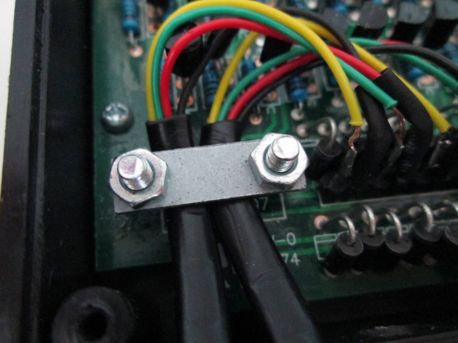
Ensure that the power socket is dislodged from its nook, being careful of the delicate wires that connect it to the main board. These are fragile and can break if tugged on.
Gently pull the main board away from its housing and turn over. You will see two bolts which hold the cable grip in place. Remove them.
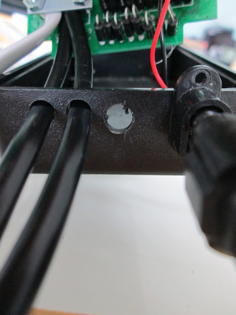
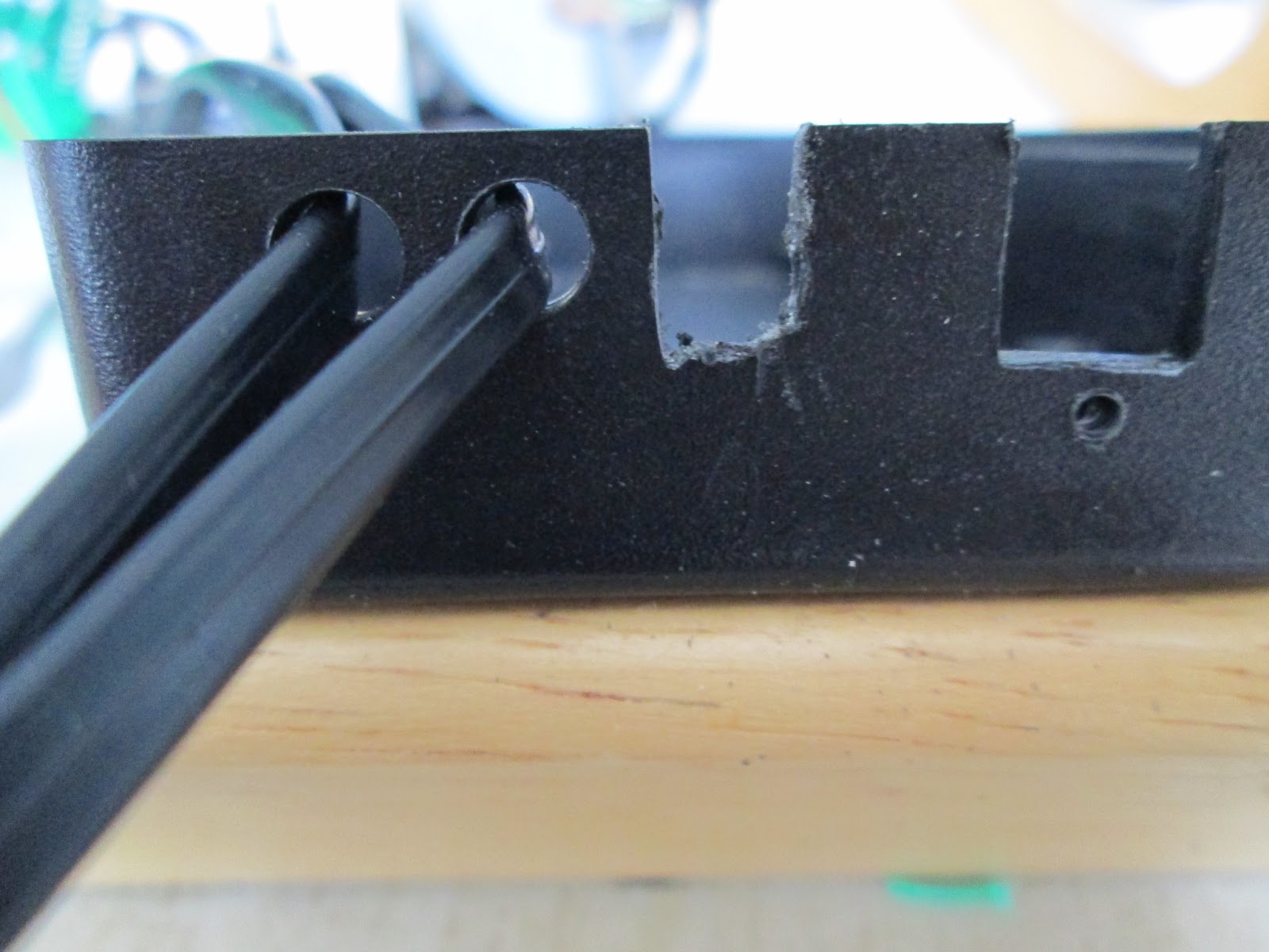
Step 5: Hole boring
You can either chose to drill a hole, or cut a slot into the outer casing of the handset. The hole may be neater, but I found that a slot makes everything more flexible. Also, if you choose a hole MAKE SURE YOU PUSH YOUR NEW CABLE THROUGH THE HOLE BEFORE SOLDERING! Otherwise you'll find yourself having to redo the job after you do it! I only mention this because it's a mistake I have made myself! D'oh!
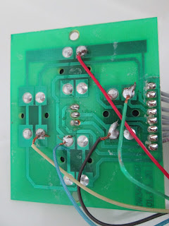
Step 6: Time to solder!
First, cut back the white (Pin 1) wire. This is unused by the handset. It is important not to have this hanging loose within the handset, as it may cause short circuiting or unpredictable behaviour.
Solder the wires into the follwing configurations. If you are a better solderer than me, which is very likely, your end result may look a tad tidier than this!
Now that you have your wires soldered in place, it's importand to test the operation of the unit. Carefully plug the unit in. Be EXTREMELY careful not to touch any exposed wires or contacts at this point. There is a risk of electric shock. Carefully press each button, and ensure that this causes the green L.E.D. to turn red. If you have a stepper motor from your mount to hand, you can always plug this in to ensure that the buttons are doing what they're supposed to. Personally, I check the functionality of the unit after every step from here on. It's easy to break off a solder joint or get a short circuit, so a quick check is a good idea.
Step 7: Put 'er back together!
First, put the three ST-4 cables beneath the cable grip and fasten it firmly. This is important as a loose grip will lead to broken solder joints in the future. A firm hold keeps everything together!
Slot the main board back into place and attach with three of the small screws. Use one more of these to reattach the lower side of the power socket.
Reattach the upper board with the two short, fat screws...
...and then replace the outer cover using the four long screws to hold it into place.
Use the remaining small screw to firmly attach the power socket, clip-press the buttons back into place, and you've completed your ST-4 Guideport modification!
PLEASE NOTE: The EQ5 is not the ideal mount for astrophotography, and it will only enable a low payload capacity to be used. I would suggest considering the use of a so-called 'finder-guider' rather than a dedicated guidescope, as these keep the weight to a minimum. If you do wish to use larger scopes with larger guiders, filter wheels and other equipment, you should consider upgrading to a sturdier mount. Of the more affordable mounts, consensus often favours the EQ6 and NEQ6 mounts, or their equivalents, which have served many successful amatuer astrophotographers well. The HEQ5 should really be seen as the minimum, and those taking on the EQ5 are either just slightly mad, or enjoy a challenge. Having said that, many people have made excellent use of this great mount. It remains to be seen if I manage to do so also!
Please also note that I accept no responsibility for any damage to your equipment during this process. I personally am notorious for breaking things and being a general bodge-artist (yes, that was the polite version), so my instructions should not be followed by anybody at any time!
-
3
- A small Phillips (cross-head) screwdriver - preferably a few millimeters will do.
-
I'm doing algebra and calculus as part of my degree - the formulae are the most evil things you have ever seen. Or in physics we have y(x)=w^2A^2sin(kx-wt+p)-w^2A^2cos(kx-wt+p). Yuckyuckyuck!
-
An 8" and 12" is a nice combination; I would like to get a 6" f4 scope to use with the reducer as well, so i'll have a nice choice of focal lengths to image at, and I'd also eventually like to upgrade to a CCD which will have a smaller chip which should be fully corrected.
I have a 6" f4 - it's taking a lot of getting to grips with, though that's probably my inexperience showing. The collimation is really finicky, unlike my 8" f6 dob. It is nice to have the relative speed though over my frac which is about f6.2. Exposures seem to take an age with that lil baby lol
-
Great start!

Debayering a DSLR's Bayer matrix.
in DIY Astronomer
Posted
Can't believe this thread is still going! Good stuff!