


Fred_76
-
Posts
125 -
Joined
-
Last visited
Content Type
Profiles
Forums
Gallery
Events
Blogs
Posts posted by Fred_76
-
-
Have you ever seen laser debayering ?
That’s ongoing here (in French indeed):
https://www.webastro.net/forums/topic/196977-debayering-capteur-au-laser/
Fred
-
Hi.
I own an antic Vixen Polaris with its original MD-5 Quartz controller. Does anyone have an idea how I could add ST4 possibility to this controller ?
There are only 3 buttons :
- Stop
- x2
- x8
This idea is to link the Stop button to the RA- ST4 pin, and x2 button to the RA+ ST4 pin. Would this work if I just link the buttons like this, or do I need a more complex electronic mount (with optocouplers, resistors...).
Clear sky
Fred
-
Hi.
I own an antic Vixen Polaris with the MD-5 Quartz controller.
Does anyone have an idea how I could add ST4 possibility to this controller ? There are only 3 buttons :
- Stop
- x2
- x8
This idea is to link the Stop button to the RA- ST4 pin, and x2 button to the RA+ ST4 pin. Would this work if I just link the buttons like this, or do I need a more complex electronic mount (with optocouplers, resistors...).
Clear sky
Fred
-
Hi Phil,
I have the same issue as you. I am trying to add the dithering capability of any ST4 compatible mount (and the Astrotrac) automatically, without any computer, with some Arduino hardware.
See here (subject ongoing, in french only) : https://www.webastro.net/forums/topic/192073-dithering-et-intervalomètre-autonome-en-arduino/
But DO YOU HAVE THE USER MANUAL of the Astrotrac TT320X-AG ? I can't find it and the previous owner of my mount can't find it...
Fred
-
On 17/02/2012 at 17:38, FLO said:
It is an f6.8 doublet with an FPL-51 ED element
Tim from WO told me it was FPL-53, not FPL-51 on the ZS 80 FD Black & Gold edition I have.
I don't know for the Red edition.
FPL-53 is far more effective (Abbe number = 94.93) than FPL-51 Abbe number = 81.54). The higher Abbe number the better to reduce color dispersion and color aberration. The Abbe number of fluorite (CaF2) glass is about 95, just slightly above FPL-53.
-
Hi all,
Here is a short movie demonstrating the slow motion of Venus in the sky. It was made during the transit of the planet through the Pleiades, from 500 photos (5 s exposure each) and a total duration of 1 hour 24 minutes.
All comments welcome !
Fred
-
 6
6
-
-
This trailing is due to periodic error. The SAM periodic error is big, about +/- 90" (or 180'' peak to peak). This is why you shall perfectly balance your equipment on the mount to reduce it a the minimum, and not use to long focal length or exposures. The SAM is not designed for focal lengths above 150 mm or exposures times above 60 s. Look a the internals here :
https://www.webastro.net/forums/topic/181169-star-adventurer-mini-périodes-des-rouages/
-
Note that dithering is only available if you have updated the SAM firmware to version 3.10 or above.
I took 10 pixels and arrived to that rule of the thumb:
d' = 35 x p / F
Where :
- d is the dithering in arcmin, to enter in the SAM console
- p is the pixel size, in µm
- F is the focal length in mm
You cannot enter decimal numbers directly in the SAM console (at least in iOS). To do that, juste enter 0 and press Done. You will see 0.00 in the box. Then just edit the figures and don't delete the decimal separator !
I saved a profile for each lens/DSLR combination I use so that I don't need to calculate that again.
Fred
-
 1
1
-
Hi all,
I proposed at Cloudynights a thread with some tricks to improve the accuracy of the Sky Watcher mini equatorial wedge that many of us use for their mini tracker.
Here is the thread : https://www.cloudynights.com/topic/700024-skywatchers-small-equatorial-wedge-improvement-solution/
Those tricks are quite straightforward and greatly improve the wedge's behaviour.
Fred
-
2
-
-
OK, nice insides, but could you give us more details than simple photos ?
- number of teeth of each spur gear
- diameter of spur gears
- reference of the DC motor (if any)
- reference of the gearbox (if any) or at least if you can unscrew its cap, a detailed photo of the internals
- reference of all roller bearings of at least shaft diameter, external diameter, thickness and number of balls/cylinders
All the best
Fred
-
On 24/07/2014 at 14:17, Photosbykev said:
The one I had from FLO for review I've opened up to see what Skywatcher have done internally. The DC motor has a gearbox going into a 24T spur gear and then a 42T and 37T spur gears going into a 144 tooth worm/wheel, the rear of the DC motor has a 44 slot encoder disk. I need to get a tacho onto the encoder and 24T gear to check out the gearbox ratio.
Did someone succeeded in measuring the gearbox ratio ?
-
No Wim, I sold all my astro equipment... here in Normandy, we have not enough good nights per year to shoot the deep sky, and I was quite frustrated to have such costly equiment standing by my garage.
I had an AzEQ6 with a SW200/1000. The PEC was working correctly with EQMod and the 71t belt, with the period set to 478.7s. I never had the time to change to the 72t belt before I sold my mount, however mechanicaly speaking, this can only improve the PEC as it will compensate the defects of more mechanical elements.
-
Hi!
It should have been better to replace the 71 tooth belt by a 72 tooth belt on the RA axis. The difference in length is minimal (2.5 mm) and the play in the motor's shaft position is enough to tension the belt.
The big advantage is that with a 72 t belt, the motor pulley, worm gear pulley and belt are back in the same position every 3 turns of the worm gear instead of 71 turns with the 71t belt. It is then much easier to do a PEC : you just have to enter the period of the 72t belt x 2 (i.e. 1436 s).
Here is a list of associated periods.
AzEQ6 with 71t belt (original)
- motor pulley (12t) : 119.7 s
- belt (71t) : 708.1 s
- worm gear pulley (48t) : 478.7 s (use this value for PEC but it will not correct belt errors)
- combined pulleys and belt : 33 986.9 sAzEQ6 with 72 belt (modification)
- motor pulley (12t) : 119.7 s
- belt (72t) : 718.0 s
- worm gear pulley (48t) : 478.7 s
- combined pulleys and belt : 1 436.1 s (use this value for PEC and it will correct all errors of the belt drive)Autoguiding with PEC "on" is possible with EQMod.
Fred
-
1
-
-
Hi Gina,
This is a working example of your idea

-
3
-
-
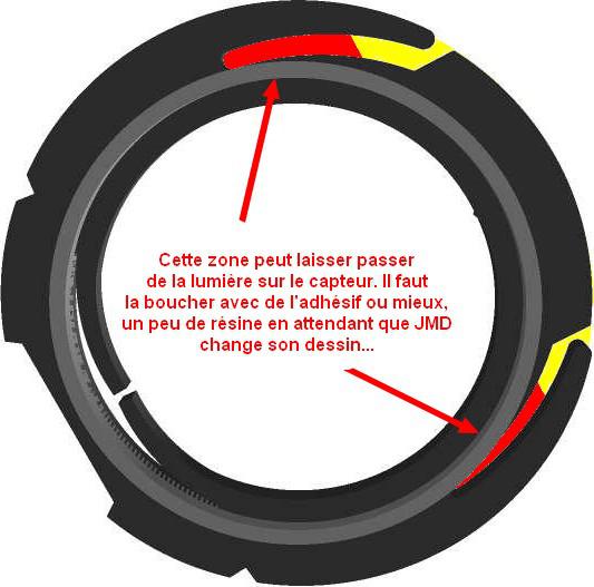
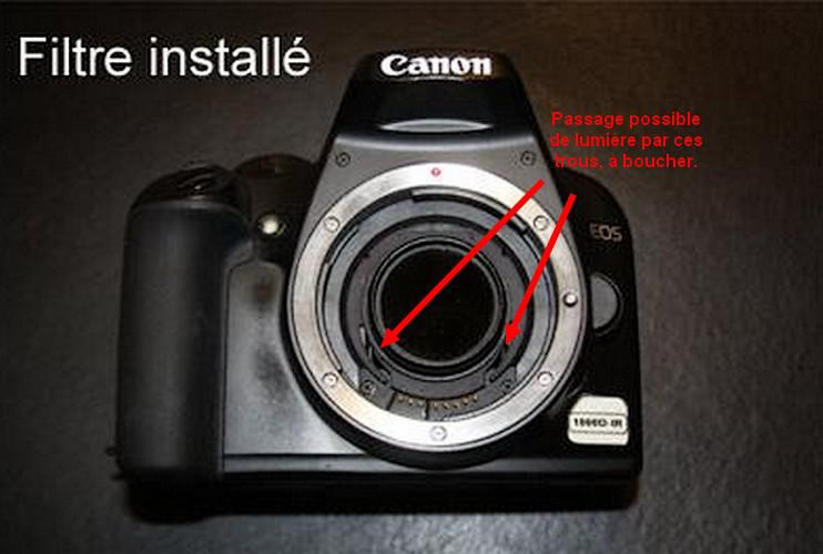
I shall need to design and print a holder for the filter.
 2015 CFA Rmoval 01.jpg2015 CFA Rmoval 02.jpg2015 CFA Rmoval 03.jpg
Hi Gina,
Here is what we made to hold 1"1/4 filters as a Clip EOS :
http://www.webastro.net/forum/showthread.php?t=123946
Fred
-
1
-
-
Congratulations Herra !!!
What's next ? Will you debayer a Sony A7s ???
-
That's great !
What kind of disorder did you found that could explain the huge 80" periodic error before your fine tuning ?
-
I tried it both ways with the same result. (i.e. washer brass side and casting side of the rollers).
All 4 roller bearings (2 large, 2 small) have a washer either side.
Hi!
What are the references of the bearings ?
It seems there is a NK 40/20 TN needle bearing, a ball gearing (40 mm ID) and a thrust gearing (AXK type, but what diameters ?).
I need these figures to calculate the periodic terms of the AZEQ6 mount for PecPREP.
Fred
-
Did you Gina do imaging with two cameras?
I have this kind of crazy idea to be tested. Two monochrome Nikon D5100 bodies with narrow band filters.
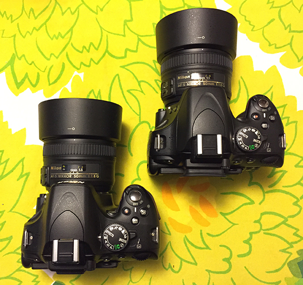

Fo you mean this ?
-
2
-
-
This filter is the one left when you do a Baader mod. It lets light passing from 400 to 670 nm approximately.
This is the blue filter (the small you broke) that is absorbing light from 640 nm approx.
-
No for two reasons :
- the contact stell/brass is almost frictionless
- the angle of contact between the cam and the stud bolt is always 90°
However, I was using a big 400s/r stepper motor, full step driven and it was generating a lot of vibrations...
In fact, buying a small motorized EQ1 is cheaper and gives better results...
-
Hi!
I did a little survey of the barndoors designs, and proposed a simpler design than the types 2/3/4 with good accuracy. It is here :
http://www.astrosurf.com/fred76/planche-tan-corrigee-en.html
Fred
-
For those who use DSS, here is a topic where I explain how to import B&W Raw files to DSS.
http://stargazerslounge.com/topic/234030-processing-bw-raw-files-from-a-debayered-dslr/
To be short, one need first to convert the CR2 or NEF RAW files into FITS files using Iris from Christian Buil (freeware). Then use DSS to import these FITS files.
The result is better than importing directly the CR2/NEF files in DSS as DSS only assumes the RAW files to be colour files.
-
1
-
-
I found a message from Gina that could help :
(see post #8)
I've put dcraw.exe in the Windows directory and a batch file in C:\Users\user\AppData\Roaming\Microsoft\Windows\SendTo containing the following code :-
@echo off:beginif _%1_==__ goto endecho Processing %1...c:\windows\dcraw -D -4 -T %1shiftgoto begin:end
Putting the batch file in the SendTo directory means that DCRaw can be accessed easily using the "SendTo" right-click option on an image file. So right-clicking on the image file name and choosing to SendTo "dcraw" will bring up a command line window where the selected file will be converted to TIFF (called "developed"). After a while the image will be saved as a 16bit TIFF file in the same folder and with the same file name but with the extension changed to TIFF and the command window will close. This makes using DCRaw a simple operation without needing any knowledge of the workings of the command line.
-
1
-


Dithering with Sky Adventurer Mini
in Imaging - Tips, Tricks and Techniques
Posted
@spordniar is absolutely right ! The formula are the same, the one I give is just simplified 😉
However I found that using 30 pixels instead of 10-15 gives better results. Therefore the formula becomes :
d' = 100 x p / F
Where :
I do not agree on the statement of @vlaiv when he says :
As the drift in DEC will always be in the same direction and at the same rate, it will generate a trail, responsible of walking noise pattern. It will not generate any "natural dither". To reduce the countereffect of the drift in DEC, when dithering on RA only, you have to dither a lot, so the 30 px instead of the 10-15 usual pixels that are commonly used when dithering in both directions.
Note that the standby time between two photos will be affected by the dithering operation. As the Star Adventurer Mini can only move at x0-x1-x2 the sidereal speed, the duration in seconds of a dithering jump will be at max four times the arc.min set in the app. For exemple if you set 5 arc.min, the duration of a dithering will be 4x5=20 s (this is a max value as each dithering jump will be random between 0 and 20 s) + some seconds to stabilize, before the next photo starts.