


Carl Reade
-
Posts
926 -
Joined
-
Last visited
Content Type
Profiles
Forums
Gallery
Events
Blogs
Posts posted by Carl Reade
-
-
Yes I understand S parameters however placing a metal rod straight through a wave guide no longer makes it a wave guide. You will have a lot of loss and the pattern will be totally random to the design.
Yes it will produce a result but nowhere near what it should be.
The mathematical design of the feed and choke does not allow for a large metal conductor through it.
-
How are you doing the tests with and without the rod?
-
14 hours ago, Coto said:
It took a lot of effort, but I decided to try even the craziest of things, like having the dish held up by a ladder (in case the rod was being problematic)...
 ... but no detection. (the focal length wasn't exactly right, but I would expect at least a tiny S/N detection).
I decided, that while I'm at it, why not just turn the feed around to zenith in case I get anything? So I tried that...
And to my surprise? It actually worked!
(P.S.: Bias Tee's SMA connector is a bit loose, and that may have caused the LNA to get/not get power every now and then..).
It's a pretty low S/N, but it's definitely there, and the bottom plot might likely have suffered a 3m LMR-400 coax + 1m USB extension with essentially no LNA (LNA must've been powered off after the first few seconds of the observation according to the waterfall).
Pretty awesome right? I decided to retry again the next day, with a bit lower S/N, but this time I got one of the outer spire of the galaxy (takes a trained eye to spot but it's definitely there):
So, the feed worked apparently, which is a sign that everything from the dish to the SDR seemed to have worked just fine (quick question by the way: I had some issues with the bandpass filter - is it meant to go between the bias tee and the SDR, or is the bias tee meant to go between the filter and the SDR?), and since I got no detection from the dish + "rodless" feed, I was confident there was something wrong with the dish.
I began questioning, "what if the hole sizes are too wide and the designer had poorly designed it 'for 2400~2500 MHz'?" (the reason I began thinking about this was due to the fact that some of the holes were wider than 1/10 * 21cm).
So what was I gonna do, tape a bunch of aluminum foils to the dish to cover the holes?
No way, I'm smarter than tha-Yes.
So I did that:
(looks like a solar cooker but it should do the work).
So, without further to do, I launch the GNU radio flowchart up, and the first thing I see is the hydrogen line!
Here's an averaged (~230 sec) plot:
I am currently in the process of analyzing (removing RFI) on a ~28-minute observation, where much higher S/N is expected and update you!
Thanks for your help Carl! But now I'll need to see what I can do with this dish considering I rather not have to deal with ugly aluminum foils every time I observe... One idea was shifting to ~400 MHz and try other types of observations, but there's more RFI in that band. I'll see what I can do...
Congratulations!! You have cracked it!!
Now it's tweaking time.
Regarding the filter it looks like you didn't need it as there isn't much interference. There is some loss in them but if I was fitting it, it would be between the Tee and SDR.
The dish, I would cover it with small mesh like fencing material to make it efficient and useable.
I would still remove the metal rod through th feed and replace with a different method. It maybe working but not fully as designed.
At 400Mhz your looking at lots of interference. You would be going into multiple Yagi territory and not a dish as it would need to be huge to be useful.
PS the ladder was a bad idea?
-
It would be fine as a line amp. He would be better off with the G8FEK amp.
-
Hi you will get there keep at it.
A noise figure of 2.8 is not good at all. The H line with a decent setup only comes up around 2 dB above the noise. You would need 1 dB or less at the feed.
A 3m dish will be excellent for the job. With your LNA on the dish you should easily pick it up.
-
1 hour ago, Coto said:
No detection today either... I also tried with GQRX but nothing interesting. There is a 3-meter cable that the 30 dB amplifier will have to account for alone without an in-line, but I don't think that's the main issue. I also tried removing the pole and holding the feed in place with my hands (didn't cover the hole though, might have to try this soon) - it was a pretty rough day having to wake up at 6 AM and work in the cold... The feed feels heavy (especially when I hold it outwards with my hands), so I'll have to see how I can try some other way and have a better luck. If it does work without the pole, your assumption will prove to be correct.
I think I've seen this before in pictures... Can you elaborate it works exactly and what connections I'd have to make?
EDIT:
What has this guy done with the red cabling? I assume he's passing one amplifier's DC power to the other, but what are the actual connections?
Yes he's linking the DC to the amp chain.
Here's a simple test, with just the feedhorn and LNA point it at the Sun and away from the sun and look at the live readings while you do it. Use very little intergration as you want to be as live as possible. You should see a rise in overall noise when pointed at the sun.
At the side of your LNA is a small pin with a lug. This is for external DC. The pin is positive and the lug is negitve. It's designed to solder the wires onto.
-
1 hour ago, Coto said:
That's what I'm going to try. Was just wondering if you had any ideas (i.e. soldering some wires to the LNA boards or just modding them somehow).
I don't think there is a tidy way round it bar giving the main LNA its own twin lead feed which people do.
-
I still think your wave guide is no longer a wave guide.
If the main LNA isn't powered there will be nothing. At the moment for testing I would power the LNA separate using its power lug at the side careful of the positive, negative.
I would remove the line amp for the moment just use the bias tee direct to the main LNA.
-
Trust me you will never see a feed horn with a metal pole through it. The can is mathematically sized along with the rod for the desired frequency putting a rod through it makes its whole dynamic has changed and effectively no use. The efficiency of the dish is irrelevant and usually worked out at 60% 70% efficiency.
Measure the input to the line amp with a volt meter and see if there is voltage.
-
Hi first things first, you have just placed a large metal pole straight through your feed horn you cannot do that. The horn needs held to the dish from the outside. You will need to fill the hole back in.
I would remove the line LNA or check the main LNA is getting 12v with a volt meter. I don't know if the line LNA allows power pass?
I can see the H line live without much averaging.
Try using SDR sharp I never got anything out of GNU radio. Peak hold should give you an indication of the readout has changed.
-
3 hours ago, Coto said:
Carl, I got my friend to put a faraday cage over his SDR:
But the RF spike still appears in the FFT. Does the cage need to make electrical contact with anything? Right now it is just "floating" there without making contact with anything.
You will probably need to do a bit of detective work to see what it is. With antenna, without antenna etc. But I suspect it's probably the PC causing it so maybe hard to get rid of. Try ferrite rings as well on the USB lead.
-
3 hours ago, Coto said:
Using a 5m USB extension sounds like a pretty bad idea in terms of packet loss - it's not even recommended for typical file transfer if I recall correctly... Wouldn't it be better to isolate the SDR from RFI using some sort of Faraday cage or something?
Never had any issues with 5m and used 10m powered for astro cameras all worked fine. Ferrite rings also good to add. Yes metal boxes where you can.
-
14 minutes ago, Coto said:
Also Carl, any idea what that huge peak around 1421.2 MHz is? RFI at another frequency (harmonics)? Could it vanish with a filter or something?
I get that at different points sometimes. I would suspect it's either PC or SDR generated RFI. It's recommended the SDR is a good 5 meters from the PC. PCs put out all sorts of RFI.
-
50 minutes ago, gabrielxp46 said:
You spoke of a site where you learned a lot, but I did not see any links, could you tell me?
Hi sorry link didn't post,
-
18 hours ago, gabrielxp46 said:
I am thinking of buying a lna similar to this:
I would like to know what software I can use to make observations besides the radio sky pipe and radio eyes
Hi radio skyline probably not much use unless your measuring total power.
Have a look at this site this is where I learned a lot and what I use CFRAD can pull out the H line with the smallest of signals and can be graphed in all sorts of ways.
Carl
-
6 hours ago, Coto said:
I also tried to use a friend's 3.2m dish who's planning on turning it into a radio telescope. He hasn't got any amplifier, filter etc. yet, just the 1420 MHz feed improperly installed and a 6m cable going to his SDR in the control room. I decided I had nothing to lose, so I wrote a quick script to take an (averaged) sample every 15 minutes for ~12 hours. Here is a gif (as expected, no detection without an amplifier but a 6m cable straight to the SDR):
Its likely to be in there you would just need the data extracted from it. If you were recording with CFRAD program you could extract it.
-
10 hours ago, gabrielxp46 said:
Besides the dish and bi-square antenna, what equipments did you use in your design like low noise amplifiers, bandwidth filter and etc? I would like more details because I am wanting to build a radio telescope as well.
Hi heres info from a previous post,
Ok best advice i would say is,
Get the biggest dish you can! You will likely have to make the dish feed yourself either the the one on this thread or the can type (measurements online).
Next is a good low noise amplifier (LNA). Around 30db gain and the lowest noise figure you can get. This noise figure will be the benchmark for the system.
You will need probably two 20db satellite line amplifiers these are cheap and work fine.
You will need filters in line as well to keep out interference. You can get these on the LNA4ALL site.
You will need a power supply 12V and a DC inserter to power the amplifiers.
You will need a receiver, a SDR dongle is fine
A computer and software.
Once you have a working scope then you can improve it as you go along.
Carl
For the first stage LNA I used one from www.g8fek.com. Then a satellite line amplifier and a filter I had already. LNA4ALL do H line filters. Requirement for filters depends on your RF environment.
-
3 hours ago, Coto said:
Carl, I see that you used the filter at the end of the electronics chain (right before the SDR). I was told by Adam (my filter supplier) to place the filter between two amplifiers.
What is the best location for the filter? I'll be using an LNA (which has one stage of amplification, then a high-pass filter, then another stage of amplification), then I'll have an in-line amp, and then (in a few weeks when it'll arrive) I'll have another in-line amp. Why does my LNA have the filter between the two stages of amplification, and not after them all like you have? Adam is also suggesting I should follow the LNA's "ideology", but I'm really not sure why.
What is the difference between placing a filter between vs after the stages of amplification?
Hi I'm assuming Adam thinks your using wideband amps which will amplify all frequencies hence the need to place a filter between them as they could get saturated with unwanted signals.
The reason I place my filter last is because anything that is picked up in the system chain ie the coax or line amps is filtered out before it gets to the SDR.
Don't forget your front end LNA is already filtered for the H line it's not wideband.
So adding a filter at the SDR just gives you added protection from signals picked up from the line amplifier or coax.
If your not getting interference from nearby out of band signals you may not even need it. There are no set rules.
Don't over think it. Front end filtered LNA amplifies the signal you want, next the line amp compensates for cable loss then filter (if needed) gets rid of any unwanted signals then SDR.
-
Well I think it's Been well thought out as a title. It does cover all now. I really cannot understand the objections.
If your using your mark 1 eyeball through glass or mirrors or both then it's visual.
The moment you add electronics to that chain it's electronically enhanced and viewing.
At the end of the day your view is either enhanced with electronics or it's not.
If you want to make a visual report do it in visual if you want to show a picture do it here.
Or you could take up radio astronomy we are down at the bottom ???
-
 15
15
-
-
1 hour ago, Coto said:
Seems like your suggestion is right again Carl. Tested with a simple wire antenna and HI filter inside the house (not at all exposed to the Milky Way) and I still seem to get that spike:
So it's probably the DC Spike you suggested. You can definitely do something in GNU Radio to get rid of it (I'll take a look how to do it soon), but is there any scenario where enabling IQ correction is not beneficial? Is there any reason why it wouldn't be automatically enabled in every software like SDR# etc., or does enabling IQ correction "sacrifice" something in order to get rid of that DC spike?
Think it's all down to mass produced cheap dongles and it was added to get rid of the spike don't think it has any other effects. The more expensive high end SDRs wouldn't have it.
-
34 minutes ago, Coto said:
So I tried some (not-so-proper) averaging to get a higher (sorta) SNR with a different wide-beam feed (that'll be used on my dish when it's ready). There's this small peak very close to f_center visible on every plot but I'm not sure what it is. Too narrow to be HI?
With HI filter (1):
With HI filter (2):
Without filter:
What do you think? All of them are with LNA.
Now that is the bandwidth you should be using.
Yes far too narrow.
I think the spike is the DC spike inherent in SDRs. As I use SDR# program it can be removed using the "correct IQ" option. Not sure if GNU has that somewhere.
-
21 minutes ago, Coto said:
Turns out you were right, Carl. After trying to demodulate the signal with GQRX, I got some pulsating sound. After further investigations, it turned out it was my dad's ham radio interfering (he wasn't transmitting, but the radio's electronics must've been producing that odd pulsating noise). Disappears when he turns the radio off... Interesting!
Ah good you found the cause. You seem to have an interference free spectrum then which is welcome.
-
17 hours ago, Coto said:
So, this is the feed designed that I used:
And a friend with a 3.2m dish (f/D = 0.3) found this:
The question is, which one is good for which purpose? I don't know how to use CST Microwave Studio to try some antenna experiments yet, but I'd appreciate your opinion if you have any idea.
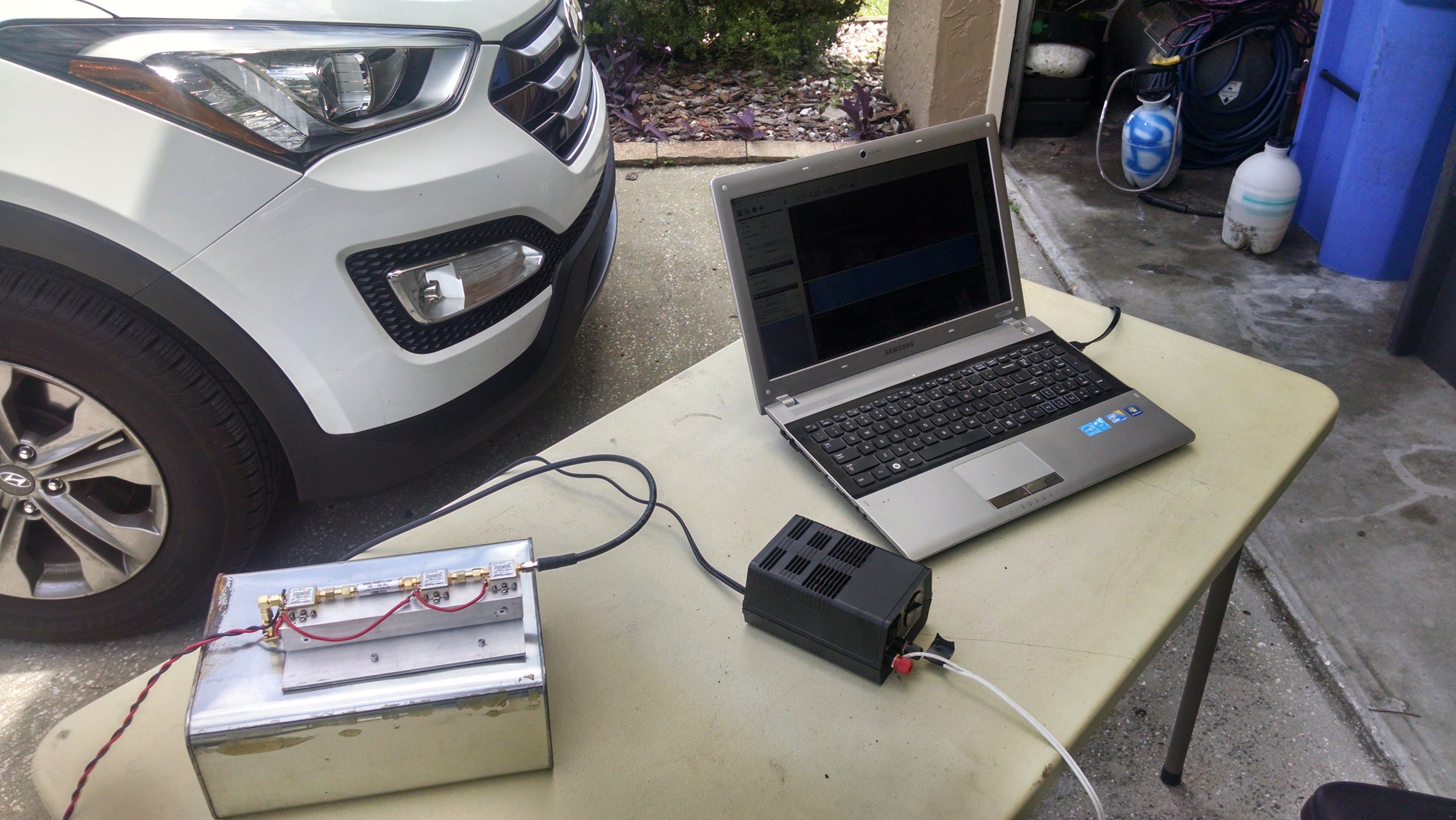
Also, I got an old feed without a choke ring that I had gotten long before, and since it was just sitting there, I decided to plug in the connector, use the LNA and 1420 MHz Bandpass filter to see if I was going to detect anything pointing it towards the Milky Way. I didn't think I had a high chance, but what do you know... I think I actually did it. There seems to be a slight 400 KHz Doppler shift on the FFT spike (which is probably normal for these types of observations), and I think I only get the spike when I point it towards the milky way (as much as I could guess at least). I've attached a few screenshots along with an image of the few things I used.
This one's averaged (sorta):
I also checked with a ham radio receiver at that frequency but got no signal, so I don't feel like this is RFI, and it can't be system temperature noise because it isn't continuous... Does the introduction of the LNA really make such a small antenna so sensitive?
Hi it looks like a very narrowband signal. You should expect the H line to be around 1420.4Ghz and more of a "hump" in the spectrum.
I have seen this method work but to bring out the H line but it needed the data processed over a period of time using the CFRAD program and then graphed in Excel.
I could not get the program your using to work right on my PC for some reason.
I would think both designs of feed horn will work fine.
You should do a sun test and direct it at the sun to see if the noise rises.
-
10 hours ago, Coto said:
@Carl Reade 2 questions:
1) Is my single 30dB LNA sufficient, or must I necessarily get at least 1 in-line amplifier? Have you had any success without an in-line amplifier?
2) I am now about to paint the feed. Must I not paint the connector region at all, or can I also only have a tiny space unpainted where the 4 nuts are from the inside? In other words, must the entire connector plate make contact with the waveguide, or can only 4 nuts make contact (which will be in contact with the ground plate of the connector)? Is there any issue regarding "how much contact is enough"?
Hi you should get a result without a line amp but I would use one to compensate for mismatch, cable loss and connectors etc.
Ref the painting there is no reason you can't paint over the connector plate and nuts as long as they are making an electric connection to the tube.


What SDR are you all using?
in Radio Astronomy and Spectroscopy
Posted
Hi Dave as I'm sure you've read I use a Nooelec dongle which is the cheapest probably on the market. It has no screening and no txco however it does work and has proved very reliable so anything else will be an improvement 😂
I would probably go for the RSP1 or duo for the reasons you stated.
My biggest nark is the lack of software that can display sub dB readings, increments of 0.2 dB for astro work. Spectravue can do it but is tied to the RF Space SDR 14. Hopefully the software will get better.
Carl