


malc-c
-
Posts
7,547 -
Joined
-
Last visited
-
Days Won
1
Content Type
Profiles
Forums
Gallery
Events
Blogs
Posts posted by malc-c
-
-
Probably worth giving the guys at RVO a call and ask exactly what they do for the money. Parts such as motors and mainboard won't be replaced for the money, and to be fair with such things they either work or don't.. My guess is that they clean and re-lubricate the bearings, and generally "service" the mount so that it performs as good as it did (or better) than the day it left the factory. They do mention an opportunity to purchase and fit higher precision bearings as an optional upgrade, but that could add a further £100 (or so) on top of the price.
I guess it's like modern cars. Other then changing spark plugs, oil and filters there is little more you can do yourself when servicing it, and chances are most garages will do the same, but they will also check lots of other components which takes time, hence why servicing via a main dealer is so costly. The same goes for your mount. You could purchase the Rowan kit and fit the upgrade yourself, and if you have the confidence, possibly remove, clean and re-grease the bearings. It may all go back perfectly and the mount could function as good or better than before your dismantled it. But it may also be a case that things don't go so sweetly and you need to send it to RVO for them to re-build it. Certainly the HEQ5 is a LOT simpler to upgrade as the gearing is fully exposed and accessible, but the EQ6, as mentioned is more fiddly.
-
I've not stripped down an EQ6, but I was inspired when I was researching converting my HEQ5 to belt drive by the guys who had converted their EQ6's and remember the task was a lot more complicated and invasive than the HEQ5. Granted the Rowan kit has been designed to be a DIY fit, but it still involves more removal of parts to gain access compared to the HEQ5. I can't vouch for the increased performance a belt mod has on an EQ6, but when I did my HEQ5 it gave better tracking, better goto precision and made the mount a lot quieter.
No one can tell you not to spend the money and take the mount for servicing and upgrade (bear in mine that £152 of that is the cost of the Rowan belt kit) or to put the money to whatever you get for the EQ6 and purchase a new mount. £220ish pounds may seem a lot for a clean and re-grease, but then there is a fair amount of labour involved, and at the end of the day they are a business so need to turn a profit.
-
Can you post a picture of your new printed secondary holder. I spent ages trying to eliminate a 5th spike on bright stars. The cause was unsilvered edges on the stock secondary. I'm just wondering if the edges of the minor axis of the secondary has been compromised by your new design.
-
It's an inductor, but as to its exact value, unless someone can measure it, or locate any markings then its going to be pot luck. Some PCB designers used them as a fuse so should something get shorted (as per the above post) they blow, hopefully quick enough to save other expensive components. You could simply try bridging L5 with a short length of wire, but without knowing how you damaged your board this fix could result in damage to the main processor.
Replacement inductors / Ferrite beads can be obtained form any electrical component supplier such as RS Components, Digikey, Farnells, or Rapid Electronics.
-
Been there got the T-Shirt. Quite frankly the response from those developing NINA was to stop using an obsolete camera and buy a new one. My argument was that if they originally considered doing that option, but then later chose not to support a serial camera cable then why leave the option in the GUI. They were so arrogant I deleted my account, uninstalled NINA and went back to the tried and tested EQMOD and APT.
APT supports serial shutter release cables from day one... and still continues to do so....
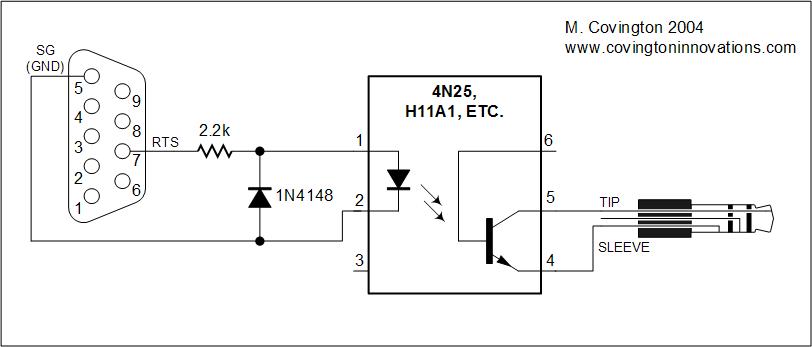
I built my cable for my Canon D400 based on this circuit

I then use a Belkin USB to (true) RS232 serial adapter. - Been working for the past 12 years without issue, as has my "obsolete" D400
")
-
 1
1
-
-
2 hours ago, Chickpea said:
Thanks again for all of the support here.
There have not been a huge number of clear nights over the last few weeks, but there have been enough that I have managed to go from "spending all night trying to get a target in view, while PHD2 refuses to calibrate and APT refuses to plate solve, with intermittent equipment disconnects and tracking stops and dead DSLR batteries every half hour" to a point where, for the past couple of nights, I can now setup quickly, usually recalibrate PHD2 on the first attempt and use Goto++ in APT with few failures.
Welcome to the world of imaging !! Glad you managed to resolve those issues and now have a quick workflow.
To be honest, I would be very happy with your first image, especially given the equipment and the steep learning curve you've been through. I think you now realise just how faint a lot of these targets are, and how much data is needed for some targets. I normally run a plan of 20 x 5min subs, 20 x 5min darks and then experiment with flats etc. I'm guessing you are not using a coma corrector as some stars at the edges look a little elongated, where as central stars are nice and round?
Wow, upgrading to an EQ6... they should make a great difference, in both precision but also stability and very able to handle the weight of the scope and other equipment.
-
Sounds like you've sorted the problem. Yes, any goto mount with a USB port fitted has one of the new generation of mainboard fitted which is ARM processor based and has the Prolific USB - RS232 TTL prolific chipset built in. The port runs at 115200 baud. Older goto mounts that lack a USB port will have older PIC processor based mainboards and require an EQDIR cable to replace the handset. Ideally these cables should have an FTDI 5volt TTL serial to USB chipset inside, but some may use the Prolific chipset. When using an EQDIR cable in place of the handset the port needs to be set to 9600 baud whether FTDI or Prolific based.
-
Ideally these mounts like being powered from a decent 13v - 14v under load. Some 12v supplies fall below 12v under load which can cause dropout. Other documented causes have been certain USB cameras which take all the bandwith and disrupt comms with the PC and mount. Also the use of long passive USB cables cause drop outs.
-
1
-
-
21 hours ago, FLO said:
This is true. In this instance, Adam's supplier is FLO. There is no issue. No argument. There has been no falling out of any kind.
FLO's service and support is over and above what is required by UK consumer law. It always has been 😇
Adam wrote to us back in Sep 2022 (eight months ago) to say he wanted to open and adjust his mount. We like to help, and we know he has previous experience working on mounts, so we agreed he could do so without it affecting his warranty. We made an exception for him.
HTH,
Steve
Steve, to be honest I knew it wouldn't be anything else. There are several examples where you guys and the guys over at RVO have gone that extra mile. I listen to a daily consumer show and it's surprising how many big names including the likes of John Lewis who don't follow UK consumer laws and push the customer to the manufacture should an item develop a fault once the warranty period has expired, even on items like TVs costing thousands.
I think your approach really does show how things should be. Adam approached you for advice before opening the mount. You were well within your rights to say warranty void but didn't, it's been documented that permission was given and the warranty would not be affected. Now whether this has set a precedent, and others will say that as an exception was made for Adam it should be made for them, only time will tell 🙂
-
I followed the link in your other post
When you say software do you mean firmware? ie the means of translating the instructions from a PC or handset to make the motors move and position the scope ? If so then to be honest you are better off looking at an existing goto system such as Onstep, which is Arduino based and aimed at those who are making their own mounts. Alternatively, if you are using a commercial mount which has the same gear ratios as one of the Skywatcher / Orion mounts then look at purchasing a control board for said mount and use that in whatever box you are placing the electronics in.
If you really want to reinvent the wheel, then you'll need to come up with a set of command codes for each of the actions for both the firmware in the mount control board and any ASCOM "driver". The "driver" would need to be compatible with existing planetarium applications otherwise you would also need to write your own PC application.
Good luck with your project.
-
23 hours ago, Adam J said:
Yes but 'how' would they (SW not FLO) 'fix it' if I had chosen to send it back under warranty?? Would they just re-adjust the screw only for it to keep working its way out again and again?? There is also the fact that if it had been done properly (using purple lock-tight or equivalent) in the first place I would not need to be doing it at all.
Honestly in many ways I have more confidence in myself when it comes to a lasting fix, but this one did stretch the skill set for sure.
Adam
Just to clarify that any warranty claim or claim under UK consumer law is dealt with by the retailer who sold you the goods. That is who you have a "contract" with and who you have paid your hard earned cash to. I can't speak for FLO or RVO or any of the other SW retailers on how they would process a warranty return if a protective sticker had been broken. Each case would be dealt with individually, and with their experience should be able to tell if the user's activity was the cause of any failure or if the covers have never been removed. In this case if it seemed that all that was required was to add some locking compound to a grub screw and make any adjustments that are needed before securing the cover and returning the mount back to you. It's then down to the retailer to seek redress from the sole distributor should they receive a high percentage of the same product back with faults (hence why we see products recalls.
To be honest the warranty a product comes with is just a guide in which the manufacture feels a free repair is acceptable. But UK consumer law is what governs the rights to the consumers expectations. If your mount failed two weeks outside of warranty it is still the retailer who deals with the case, and in some cases (not directed at any astro kit supplier) they might try fobbing the customer off as its no longer in "warranty". In reality in such cases I'm sure FLO or RVO (and other reputable retailers) would still agree to resolve the issue free of charge (and thus increase their reputation). However, as mentioned before, goods are expected to last for a reasonable amount of time based on the retail selling price. For example you would expect a £2000 TV to last a lot longer than a £200 TV. The same may translate to SW mounts.
As a side note, you mentioned seeking advice and authorisation from the retailer to brake that seal in order to affect a fix, which was given. Again, its worth getting such agreements in writing, should something else happen and the mount needs a return for the same issue or unrelated issues and then the retailer tries to refuse the warranty claim (again, this is not directed at FLO / RVO or any other large retailer who prides themselves with an excellent reputation for customer satisfaction).
-
1 minute ago, apaulo said:
I think the manufacturers warranty reflects the makers life expectancy of the product. I bought an item a while back it came with 6 years full manufacturers warranty, that tells me, these guys like this product. What do we get with over priced astro tat, 12 months . It speaks for itself.
The good thing in favour of the consumer is that there are so many mounts whos design hasn't changed over decades that are still functional after 10+ years of service, so when a mount fails 30 months down the line you are in a good position under UK law to have it fixed without charge
-
1
-
-
Adam, I've reported your OP to the team with a request to make the first post a sticky post so it's always available as it will prevent others damaging their mainboard or connectors.
-
1
-
-
8 hours ago, Adam J said:
SA actually mounted the Main Board on the back of the cover that you need to remove to access the worm gear assembly. This is bad because its not possible to see that the main board is located in such a way until you start trying to pull it off!
WARNING: DO NOT TRY TO REMOVE THE COVER WITHOUT FIRST REMOVING THE MAIN BOARD FROM THE INSIDE FACE! If you do then you will likely pull connectors out all over the place and potentially damage the board as in their rush to save every penny SW have not made the cables just 3cm longer to allow you to fully remove the cover before having to unscrew the board. As such getting it off is almost impossible, but that is nothing in comparison to putting it back on again ill warn you. Even worse you cant perform common maintenance such as refreshing the lubrication to the RA worm without having to go through this.
That's common practice with a lot of thing, not just telescope mounts. Mounting the mainboard to a cover plate is nothing new. The EQ6 has the mainboard attached by standoffs to the metal cover, however in these mounts the cable harnesses to the motors, encoders etc are of significant length to allow the plate with board attached to be removed far enough so access to the connectors is possible without damage to them or the board. Conversely there are mounts like the HEQ5 where you have to remove all the gearing and stepper motors just to gain access to the two screws that secure the mainboard to the mount. The one thing in common is that Synta don't want to make access simple and easy. It is also common to have that claim of "warranty void if cover has been removed" with a little sticker over one of the securing screws.
One thing I would add is that people should be mindful of UK consumer law, in particular the section that basically states that a consumer would expect the product to last a reasonable amount of time based on the cost. If you have spent several hundreds of pounds, if not thousands, on a mount you would expect it to last longer than the normal 12 or 24 month warranty. However if after the warranty period you brake that seal then they are with in their right to charge for any fix rather than be cornered to repair it free of charge should the mount fail just a couple of months outside the warranty.
I do think the "no serviceable parts" is a misnomer. I've repaired several mainboards, often replacing the microcontrollers so these boards are serviceable. Granted the newer mounts use ARM processors and need more than a soldering iron to repair them, but it's still doable.
Thanks for posting your findings.. maybe the admin can make your OP a sticky in the relevant section so that the warning doesn't get buried.
-
1
-
-
I'm sure they will sort it out...
-
1
-
-
IMO if the mount responds to the commands to rotate in RA when doing the plate solving, but then fails with any goto commands then there is no hardware fault with the motherboard. Before you send the board back to RVO can you try one thing. On a normal windows PC (not an ASIAR device) install ASCOM and EQMOD. Connect the mount and using the EQMOD Toolbox utility set up EQMOD to use the correct port and setting for whatever cable (EQDIR or USB) used. Then launch EQMOD, set the slew speed to 4 and click and hold each of the NSEW buttons to see if the mount moves. If when trying to connect to EQMOD via he Toolbox utility EQMOD keeps launching and then closes with a comms error then this would indeed confirm the issue is with the motherboard in the mount.
If it seems to work without any errors then try running the attached application which uses raw commands to interrogate the mount and produce a report like the example below
If RVO say the replacement is chargeable as the rig is outside the normal warranty period you may still have a case under UK consumer law as given the price of the mount you would expect it to last a reasonable amount of time or use, and clearly as this has low mileage you have a strong argument.
Regretfully as you have mentioned the fact you have tried a USB cable to connect the mount to the PC (which basically is what the ASAIR is) the control board is likely to be one of the ARM based boards and I lack the equipment to be able to replace the processor and reprogram the board for you. This would be a last resort should the purchase of a replacement seem the only option left.
You are right about the design, in that there is very little protection against over voltage or to prevent the serial ports in the processors being blown. And the replacement cost is anywhere between £100 - £160 depending on the mount. However I'm sure the guys at RVO will sort thing out for you should the board prove to be faulty.
-
1
-
-
2 hours ago, JeremyS said:
Would love to hear about your work with Tasco, Malcolm.
Like so many others, I started out with a Tasco 60mm refractor which I was given for Christmas 1973.It was nothing glamorous. I started there in 1981 as an admin in the main office in Welwyn. The main warehouse / accounts / payroll etc was based in Newbury. The office was basically a base for the individual directors of companies that formed the Tasco group other than the sports brand Head which was based in Newbury. My main duties involved processing customer orders, answering the phone, and managing the sample stock that the directors took with them to sales meetings etc. I became the "technical adviser" when Halley's Comet came round, taking calls from people wanting to know what to expect and how best to observe it. I then was given the title of Product Manager when we employed a new admin to take over the admin duties, and I then assisted the in house designer to produce the full colour brochures etc. It was at this time I tried to get the directors to carry a more professional range of telescopes but in the end it often came down to profits and given the numbers it never really met the criteria. The best selling scope at the time was the 11TR, which whilst the optics were OK could never really be classed as a serious astronomical scope, mainly given the wooden tripod and mount.
I then move to the toy and hobby company, and basically became the directors right hand man. I attended the regular toy and hobby fair in London, mainly as I had an interest in RC models and Astronomy so could answer technical questions. Sadly as I started as a junior position (advertised for a school leaver - I was 21 at the time) the salary never really increased to where it needed be and I ended up leaving Tasco in 1987.
The MD and his wife were fantastic people (sadly passed away a few years back), as were the rest of the staff. It felt more like a family than going to work. Anyway, sorry for the OP taking this off topic... but yeah it was a period of my life I enjoyed.
-
 1
1
-
-
No problem. What you have sounds fine, and it's not really going to need "upgrading" immediately.
Lets hope for some clear skies so you can christen the thing 🙂
-
1
-
-
On 13/05/2023 at 19:01, bosun21 said:
Tasco binoculars of old were good when they were made by Vixen,
That will be back in the 1980's then... I worked for Tasco around that time and whilst I had the title "Product Manager" I struggled to persuade the directors to bring in one or two of the higher end telescopes and binoculars that Tasco made for astronomical use. Having said that, at the time their standard 10 x 50 zip focus proved a decent allrounder.
-
2
-
-
This is a really puzzling one as you state that it was slewing in both axis when doing an alignment routine, but subsequent goto's only the DEC was fine, and with the handset both axis are not responding.
With the handset connected directly to the mount and the mount powered on the handset will send an initial command of :e1 and :e2 which communicate with the microcontroller (either two 16F886's or an ARM chip) and should result in the card version and firmware version being returned. If nothing comes back then the handset displays the "No response both axis" message. I was going to suggest the issue could be with the EQDIR / USB cable used to connect the mount to the computer, but the fact you get the same issue with the handset (assuming the correct cable and port is used) would rule that out.
From the first image I can's see any cable connected to the mount - can you elaborate how you are connecting the mount to the control computer? - If using a bluetooth or wi-fi adapter try removing it and using a dedicated EQDIR cable, or if your mount has a built in USB port, then use a short A-B USB cable and set the corresponding port that the computer assigns to 115200 baud rather the the default 9600 required for the EQDIR cable. If you are just using the handset and standard curly RJ cable, thus removing the computer from the equation, and neither now respond then it would seem that the mainboard has developed a fault (probably a blown Q3 if its a new board with USB).
-
1
-
-
Part of the problem is that there is that there is still some element of error when using a perfectly aligned polar scope (especially with older polar scopes) as the "bubble" in which polaris is placed is so large that you could fit three or four Polarises across the diameter. Whilst this is fine for visual, for imaging it needs to be a little more precise.
Yes there is a fair bit of confusing, even on forums. There has always been conflicting opinions of having to have an EQ mount true and level. Before I placed my rig in its own observatory my workflow was to place the mount level with the N leg of the tripod facing North, then without the telescope fitted perform the polar alignment. Once I was happy with the alignment the mount would be placed in the default home position (weights down in line with the N leg of the tripod and DEC axis correctly rotated and also in line with the N leg of the tripod) I then fitted the scope. Power was then applied and a 3 star alignment performed, and the scope then set back to the home position form the controller before selecting the target to observe.
-
14 hours ago, Louis D said:
A lot of these cheap, variable voltage power supplies are not well regulated. Their voltage can vary while under load, not supply enough amperage, introduce electrical noise into the line by being a switched power supply, burn out prematurely due to cheap components, etc. You just need 2A at 12V, so find a quality 12V transformer type power supply rated for at least 2A with the proper connector, and you should be good to go.
I would recommend shelling out £30 - £40 for a 12v 5amp supply form Rother Valley optics or FLO. That way you know you have something suitable for the mounts that they sell, and should something go wrong and it stops working then you have a better change of having it replaced with as little hassle than through the Amazon return process, or direct to a Chinese supplier.
5 Amps will give you enough headroom to cover the surge in current when the steppers start the slew. The current draw once moving for both steppers is around 1.8 - 2.0 amps. The mainboard only draws around 40mA so doesn't really impact the load. The other advantage of buying form FLO etc is that you'll know it will work, and has the right barrel connector. The mainboard lacks any real reverse voltage protection, other than blowing a large diode or inductor, which then means a repair or replacement board.
-
2
-
-
Graeme, any length of timber used as a beam will be able to support more if used vertically due to the grain structure. Ideally the beam should be placed on top of the two posts so that the weight gets transferred through the posts (like a compressive force). If you place the beam between the posts then you are reliant on the screws or bolts taking the weight. Diagonal bracing will help tie thing together if it's impossible to make these changes at this stage. Neal's suggestion of turning the existing beam into a T beam by using a 4" x 2" is a good idea. You could go one step further and add a second beam identical to the existing to for an I beam. Use a decent waterproof adhesive between the beams and secure with screws every 12-18".
Granted this may seem overkill, especially as they only support the roof when the observatory is in use, but over time the weight could cause the beam to sag and cause problems, so having a belt and braces approach and over engineering things is the best method
-
2
-
-
I agree, the wood used to support the roll off roof needs to be a little more substantial, or the existing supported by some cross-bracing. Other than that I think you've done a fantastic job.
-
1
-


Modified SW130pds
in Getting Started With Imaging
Posted
Thanks for uploading the images. The star image is not the same as when I was having similar issues. Yours is even, and both sides. I'm no expert, and hopefully someone with more knowledge of these thins will chime in, but my thought was that the focus tube is protruding a fair bit into the light path. If I can use a clock to explain my logic, your 3d spider has vanes at 2, 4, 8 and 10 which looking at the image results in spikes at the same 2, 4, 8 and 10 O'clock positions. The focus tube axis is a line through 9, and 3 which again the rouge spike appears in the same position.
As I said, I'm no expert in optics, so my logic could be way off.