


keith5700
-
Posts
49 -
Joined
-
Last visited
Content Type
Profiles
Forums
Gallery
Events
Blogs
Posts posted by keith5700
-
-
Steve,
yes thermals are a bit of a problem when using high mags on planets. The fix is going to be some tubes at the top, with some sort of spiral deflector maybe, to route the thermals around the tubes and off at the top. It's not top of the list at the moment though.
Not sure what your other question is asking? it is vastly more difficult to collimate this scope properly, than a standard Newt. The extra mirror each side wasn't much of a problem.
The difficulty was getting both sides collimated, at the same time as getting the optical centre lines parallel to each other, and getting them parallel to the centre line of the centre ally tube. Or more specifically, to the centre of the axis on which the main mirrors travel up and down.
It did take days to get everything lined up properly, and I had to make several optical aids, multiple lasers and long bubble tube levels, etc.
It is possible to form a single image when both sides are not quite parallel, by simply tweaking one of the secondary mirrors. I can only assume the plywood versions of this design rely on constant adjustment when used by multiple observers.
Certainly I would say now that perfect collimation/alignment has been the most difficult part of the project so far. But on the flip side, with it being all ally,and very rigid, I will never have to do it again. Unless I drop it.
-
Olly, the coning angle on my eyepieces was tried in order to make the viewing conditions more favourable. Making the optical focus point coincide with where the brain seems comfortable observing the image is just a theory I came up with, but it seems to work far better than having parallel eyepieces.
However, in your case, not being able to form a single image at all is nothing to do with any of this. I think you'll find the binocs just need collimating.
Cheers.
-
Just got it all tidied up, and finished the electric focusser.
The drives seem to work fine, bearing in mind they are just being driven off a rubber belt at the moment.
Focusser works well too, it converts to manual by pulling out the pin.
Now to have a go at imaging Jupiter.
-
 1
1
-
-
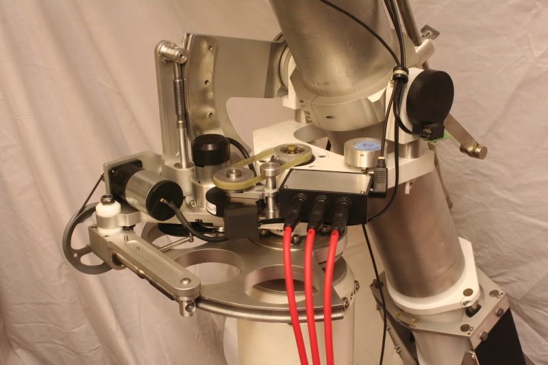
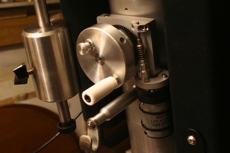
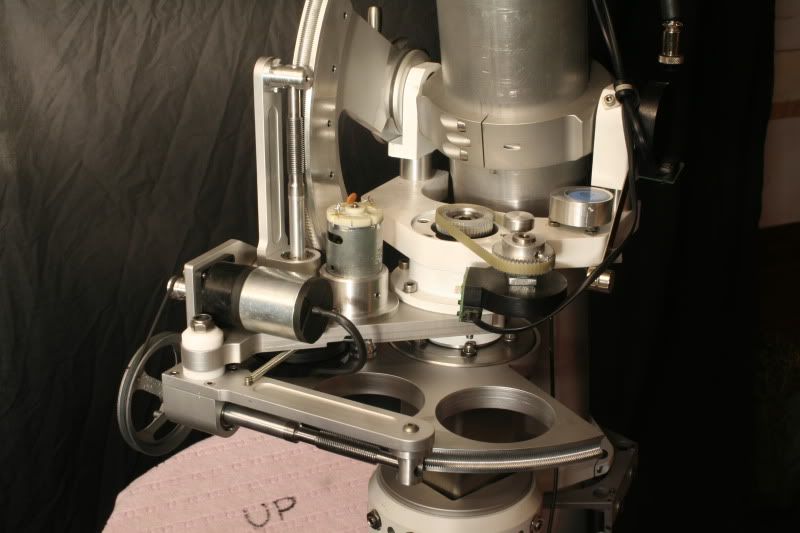
Guy, the bearings are thick PTFE pads held in ally holders. Each holder is adjustable in and out to get the square tube running concentric to the outer round tube, and to adjust the preload of the pads.
The square tube is 60mm stainless.
An easier way would be to run the tube directly on to the outer race of some ball bearings.You'd have to use them in pairs with a spacer, so you'd need 16 bearings.
40m o/d bearings would be ok. You could put eccentric bushes in the bearings to adjust the shaft position/preload.
The height adjustment is by a 20mm square threadform shaft, turned by a car seat gearmotor.
-
1
-
-
Thanks for the comments, again.
I should mention that the motor/gearboxes are only temporary. I'm still trying to get my head round how to get a stepper motor to rotate at different speeds. It seems a simple enough task but but I'm lost in controllers and drivers and Arduino boards at the moment.
George, no I haven't got access to CNC, it's all done manually on my Bridgeport miller.
Kevin, I think the resolution is the same as a single 16" mirror. I don't think you can take account of the spacing between the mirrors to increase the resolution if each eye is only seeing light from one mirror. That's my theory anyway.
Electric focusser next, I'm drawing this up first so might look a bit neater.
Cheers for now.
-
1
-
-
Right, got a few pics of progress.
Although it looks quite, it shows the pitfalls of not designing something first, ie. I made the tracking bits as I went along and it's starting to look a bit messy.
I cut the wormwheel segments on the lathe first and tried to fit them in suitable positions, but as I went along, bits were getting in the way and some items have odd cutouts or spacers in them to clear other bits.
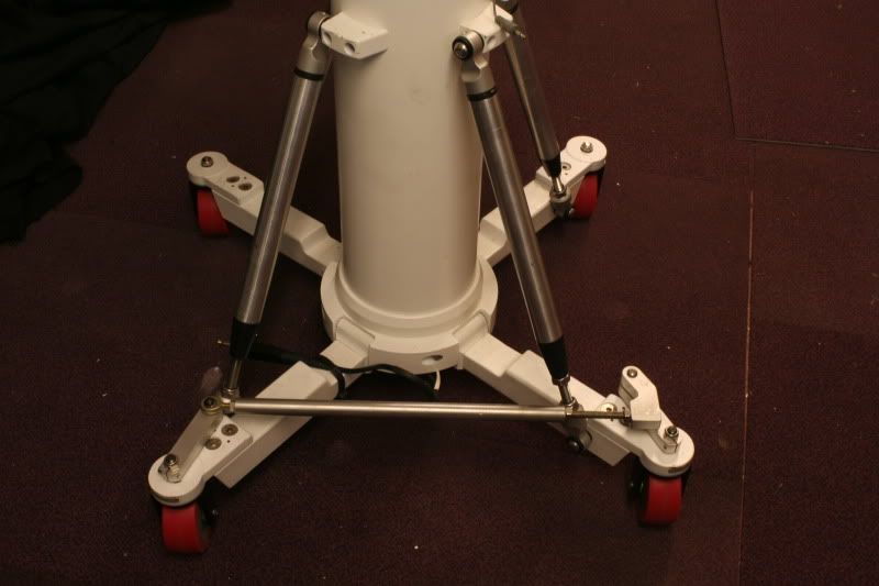
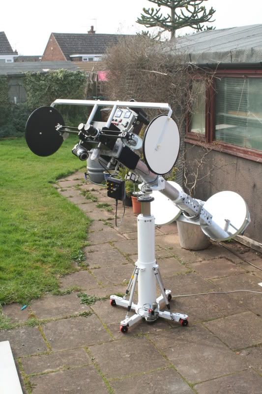
The steering bar was added to 2 of the wheels as it was nearly impossible to steer 4 independant wheels before. It's dead easy now and is a worthwhile addition.
I have been asked why 4 wheels and not 3. Well 3 wheels would have to have been much further out to get the same stability and would have got in the way of the user's feet. Also it wouldn't fit through the garage door with 3 legs.
-
Sorry, didn't notice recent replies on this thread.
I've put in a fair amount of work on the scope in the last couple of months, but most of it has been improving the workings of it, as we have a bit of viewing experience under our belts now.
We have just bought a Celestron Neximage, so are playing with that at the moment.
The first thing which became obvious was the need for some sort of motor tracking system.
I had a look round the shed and found a few motors and bits and bobs and desiged a drive around them. I cut a 12" wormgear on the lathe last week and split that into 2 useable segments for the alt and az drives. I would like some stepper motor drives on it, but haven't had time to get my head round what's required to get them to work yet. It looks a bit tricky with controllers and drivers and programming etc.
I'm just going with the 12v dc motors I've got, at the moment.
I've replaced the 2" wheels with 3" to make it easier to push around the patio, and fitted a steering rod to 2 wheels, as trying to get 4 wheels to track properly was a nightmare.
I'll get some pics up if I finish it this weekend.
-
No, won't be going to Kelling. Looks like a long way from Derby, presume that's the Norfolk one?
Not done much on the scope over summer, been spending time in the garden.
Still trying to persuade my mate to buy a couple of Ethos 8mm eyepieces. Be nice if we could borrow one first though, £900 is a major expense if it wasn't anything short of amazing.
Done a write up for Astronomy Now magazine. Hopefully it'll appear later this year.
-
I think somewhere between 3 to 3.5 metres diameter should be ok with the scope, and he's got plenty of room for that.
Yes you are observing directly behind your head, as are pretty much all other reflecting binos that I've seen.
-
Peter, yes I ought to do a proper write up sometime. It would have saved me loads of time if I'd have had something to read up on before I'd started this. I suppose most of the difficulty, assuming someone had the engineering skills to actually do the construction, is in the lining up and collimation afterwards. In fact we've only just got it fully lined up this week really, and we've been overcoming collimation type problems we never even considered at the start.
The good news is my mate said today that he's persuaded his wife to let him build an observatory in his garden. That means I can start designing my dream scope, which is a 24" binocular. This one will be done properly, over a number of years, using materials bought for the job, rather than having to use what's lying around in the workshop!
It's a 2-3 year project, but means at some point the 16" scope will be up for sale, to finance the 24". Just a thought, if anyone did want to own it in the future.
-
Thanks again for the encouraging comments.
Riklaunim, good idea with the webcam, I'll try and get hold of one.
We were looking at the Moon the other night and I decided to do some experimenting with looking through one eye only, and then both eyes. The difference is really like chalk and cheese, it's so much better with 2 eyes. I can't bear to look through a single eyepiece scope now, it feels really weird and difficult to pick stuff out.
The 'spacewalk' analogy has been used many times, but it sums it up perfectly.
I was going to encourage others to try and get a look through a binoscope, or binoviewers, but thinking about it, it might not be such a good idea after all, if you know what I mean.
Next bit is sorting out the camera holder with an eyepiece so we can start imaging some planets.
Cheers, Keith
-
Just a quick update.
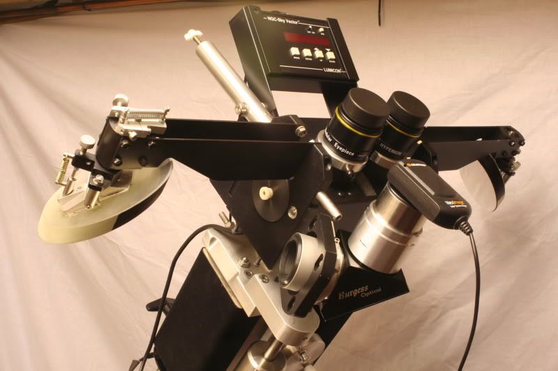
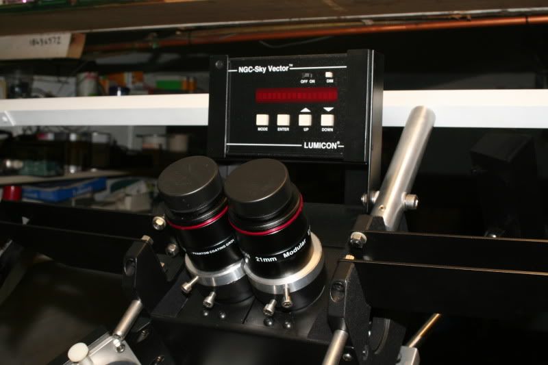
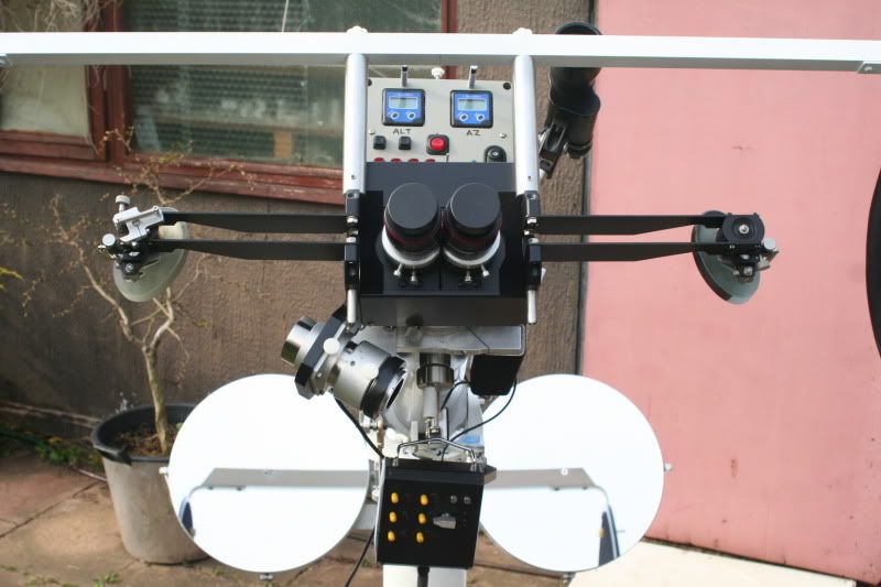
My mate's had the scope for a few weeks, getting himself familiarised with assembling it on his own. The biggest pain was those Wixey type angle readers, so we decided to scrap them and get the Lumicon NGC Sky Vector.
I've now got the scope back and have fitted this, and done some little mods here and there to make it all more user friendly.
The encoders look a but vulnerable mounted where they are, but it'll do for now. Can't believe all the button pressing you have to do to locate an object on the Lumicon, but I guess it becomes easy once you've done it a few hundred times.
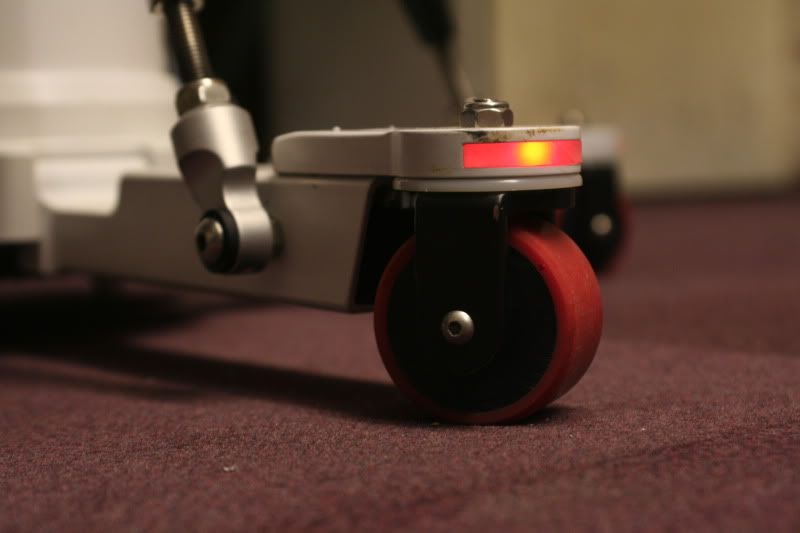
The last photo shows how the feet light up, although someone's obviously given it a good kick judging by the scuff mark. Maybe they weren't switched on!
Wre were getting a bit concerned that the scope didn't seem to be giving a pin sharp star image, but I now suspect this is from body heat rising in front of the scope. A de-focussed star image seems to be boiling all over the surface. It's difficult to test the theory as I can't get much out of the way and still see into the eyepiece.
Maybe some sort of heat deflector needs to be drawn up.
Cheers.

-
Very nice!
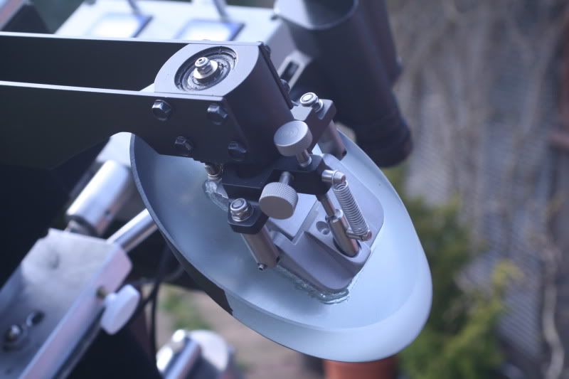
Do you observe from a dark site, or so you find any problems with scattered light? I see you have the baffles behind the secondary mirrors, but are there any others??
I would have thought one of the problems is co-aligning the two mirrors so that the field of view is reasonably common between the eyes? I guess the brain is more tolerant of a mis-alignment than a camera, but how good does it need to be?? I guess you have collimation screws on the primaries?
What resolution are the alt/az encoders?
Sorry for lots of questions -- just interested

I haven't got a dark site but we're going to one at the weekend so will have a better idea then.
There aren't any more baffles yet but that's next on the list.
The primaries, secondaries and tertiary mirrors all have collimating screws, and a laser collimator is a must have item.
The brain can merge 2 images which are quite a way off from each other, but you'd soon get a cracking headache.
My experience of the 2 images is that the need to be absolutely crack on, leaving nothing for the brain to try and merge. Hence the all alloy rigid construction and painstaking attention to the initial setting up of the mechanics and optics.
The alt-az meters have a resolution of 0.1 degrees.
They seem very accurate for the money.
-
It sure is an impressive looking bit of gear and i salute your workmanship.
Would it be rude to ask about costings for the build?
finished item,i mean.
No, not rude at all.
The 6 mirrors were about £3600. These were bought by a friend of mine who has financed most of the build, and kept me on a practical level when my imagination starts to run wild with things i could incorporate into the design.
I've spent about £500 on the mechanics and electrics so far.
Most of the cost to reproduce one of these would obviously be in the labour. Not sure how many hundreds of hours have gone into this so far, and there's no drive systems or goto on it yet.
I've seen a 16" bino from JMI? in the USA which they sell for $16,000.
To finish this properly with an encoder type goto drive system, and light shrouds etc will need another £3-4000. So I'm guessing it won't ever be finished!
-
Sorry I'm doing multiple posts but I typed a long reply and lost the lot an hour ago.
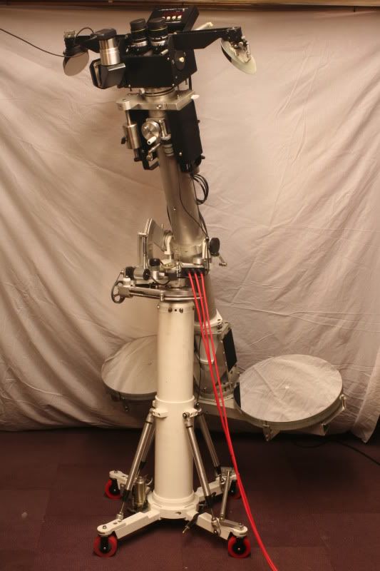
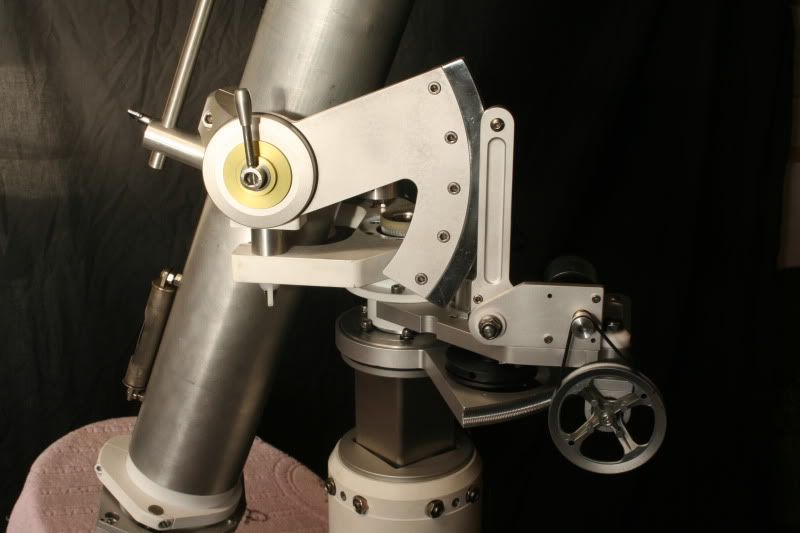
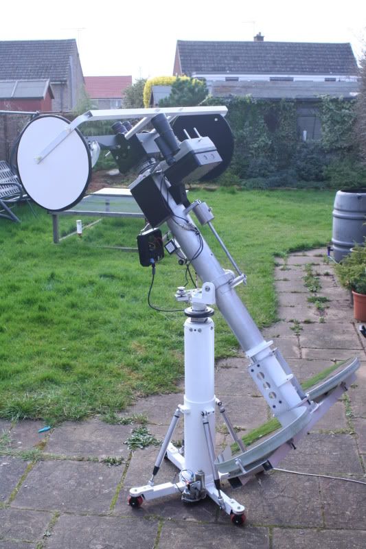
The other thing on the scope is the centre mast raises and lowers. This is so whatever altitude the scope is at, it can be raised or lowered so the viewer can remain standing.
Provided you wait for the mast to move. It needs a bigger motor on it really as it takes a couple of mins to go from full down to full up, about 600mm.
This isn't the ultimate design for a binoscope, far from it. I ran out of money with the mirrors so the scope is made mainly from bits and bobs lying around the workshop.
I'm sure it could be simplyfied/improved by purchasing better sizes of tube etc.
-
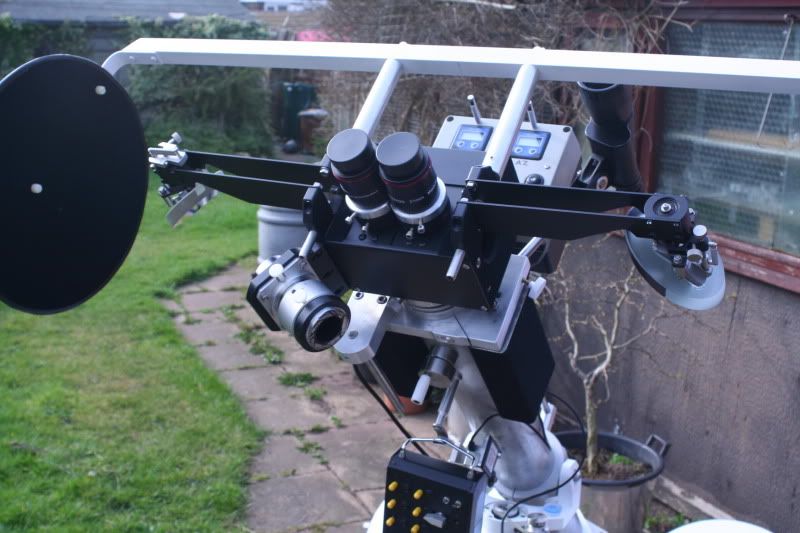
One thing I've not seen on other binoscopes is the coning angle I've put on the eyepeice holders. The eyepieces have an included angle of 4 degrees.
When I did the last 12" bino I used to get eyestrain fairly quickly and eventually guessed it could be from looking down 2 parallel eyepieces but trying to form an image, say, a metre in front of me. I think it was confusing my brain!
So I angled the eyepieces in on that scope and it cured the problem. It was really comfortable and natural to look through after the mod.
So I did it on this one from the off.
The worst bit was getting everything aligned. As the main mirrors track up and down the centre tube then the mirror sets had to be not only aligned with each other, but parallel in both planes to the centreline of the main tube.
We had water tube levels, plumb bobs and all sorts of lasers filling the workshop on that day!
I've set the left hand side as the datum and any little tweaks to get a nice comfortable image are done on the right hand secondary mirror.
This only needs doing sometimes after changing eyepieces.
Thanks for all the comments.
Keith.
-
Well thanks for the replies.
Afew quick questions answered first.
Yes I am a design engineer and have a full workshop for hobbies, including the Bridgeport.
Yes I did make a 12" version of this a long time ago.
No I've not noticed any funny diffraction spikes from the 2 arms but will try and take more notice next time out.
The alt-az gauges are about £50 each and they're just a general engineering type of angle display.
The Az encoder is belt driven off the main axle and there's a clutch under the knob so the encoder can be turned without moving the scope. So I set the scope to a known object, find the angles off the laptop, and then turn the encoders to read that angle. They work fine, but switch themselves off after 10 mins of not moving, and reset to zero, which is a pain.
-
Hi all. First post so go easy on me.
I'm building a 16" binoscope. I've been at it since Xmas and thought I'd put some pics up of progress so far.
I'm sure most of it's construction is self explanitory from the pics, but a couple of things are maybe worth a note.
The main focussing is done by raising and lowering the main mirrors, which are fixed to a frame which slides on hardened shafts and linear bearings. The focussing knob is at the top and this drives a screwed shaft through the centre of the main tube.
The eyepiece width is achieved by sliding the eyepiece holders apart and together, again on shafts and bearings.
The diaoptre adjustment is done by moving the eyepieces left or right as a fixed pair.
So, the first adjustment is to set the eyepiece width. Then, whilst looking at a star, the pair is moved left or right to get both stars equally out of focus, which is easy as the images are concentric.
Then the main mirrors are adjusted to bring it all into focus.
Sounds complicated but it only takes a few seconds, after a bit of training.
There is a control box for the eyepiece adjustment so they are moved by turning some knobs, and 3 settings, for 3 viewers, can be stored and retrieved from the controller.
Anyway, I'll see if I can get some pics to load.
Keith.
-
8
-

DIY 16" binoscope
in DIY Astronomer
Posted
Wow doesn’t time fly! Here’s a quick update on the binoscope.
I did a full overhaul last year, converted to 3 legs to make it easier to level.
I’ve built an anodising setup, so did some colouring of various parts. It has a Nexus 2 push to system, which is great.
I still hardly use it though, I think my biggest pleasure is in making things. I think it may be time to sell, but where, and how much, I’m not sure. I can’t face putting it on Facebook Marketplace, with all the stupid offers I’ll get, so any suggestions welcome.
I don’t really know how to price it either, I reckon it owes me between £6-7k, so maybe somewhere round there?
cheers.