


russellhq
-
Posts
1,432 -
Joined
-
Last visited
Content Type
Profiles
Forums
Gallery
Events
Blogs
Posts posted by russellhq
-
-
Based on my experience comparing photos from debayered and Baader modified sensors and also taking into account what Luis has said, I find the results from RawDigger a bit confusing. Is it possible that this software has been designed to work with a Bayer matrix and it isn't showing correct results for debayered sensors? Just a thought.
I'm not sure what you expected the results to show? I think they are in agreement with your observations.
-
Does anyone the power consumption in amps of a cooled DSLR ?
Dave
A 2A TEC seems to work. So TEC + fan + camera + controller would be about 3A.
-
Guys, the settings are the same: ISO 200 Speed 1/125 F5.6 Same lens
I'm not contesting that there is a loss of sensitivity brought about by the removal of the microlenses. I just want to make sense of all this.
I would hazard a guess that as you are gathering 50% more red light and 50% more blue light and have no loss of green light, then since you're imaging sun light your image will be brighter with the debayered sensor.
-
Finally, after what has been discussed here, I am a bit confused. Maybe you can help me with this. It has been said that the loss of the microlenses could account for 30-50% of the sensor sensitivity. Yet, here you have a comparison of pictures taken with my 1000D debayered and a Baader modified 450D. Even if the cameras are different, I would expect the 450D to be superior to the 1000D so I think my point stands. These are the set of photos in twos; comparing both cameras: greyscale camera jpeg from the 450D versus custom WB jpeg from the 1000D. Also raw from 450D versus raw from debayered 1000D. I think they are interesting. How is it possible that the 1000D has lower sensitivity if in all the comparison photos, the result is invariably brighter? By the way, all photos have been taken with the same lens and the same settings: ISO 200, F5:6, same speed (I don't remember now)
You are probably experiencing differences in brightness because you are not imaging the same scene with the same settings and sensor.
My previous post demonstrated the sensitivity loss on the 1100D to be around 50% on a pixel by pixel basis. In this case, I used a camera with a sensor that had half of the CFA removed, this guaranteed that the same settings and light conditions were seen by the debayered and original pixels. I also used narrowband filters to ensure a straight comparison could be made between the pixels with CFA and those without. The RAW images files are linked to at the bottom of the post if you wish to inspect them.
http://stargazerslounge.com/topic/166334-debayering-a-dslrs-bayer-matrix/page-81#entry2308747
-
I use some thin, hard plastic to keep the cold finger away from those tiny SMDs. This was from offcuts from secondary double glasing sheet but any thin, hard plastic will do. I made a T shaped piece so that the lugs stuck out beyond the gap and stopped the plastic sliding in too far when inserting the CF. Plastic in first then CF between plastic and sensor with thermal paste on the CF. The SMDs and plastic insulation limit the thickness of copper sheet for the CF - I used 0.7mm. In spite of the thin copper I managed to get the get the temperature down to -15C with an ambient of +14C.
Thanks Gina, just the info I was after. I've been prototyping with 1.2mm copper (which is a pain to bend!) and that's a tight squeeze with the dead sensor. I've ordered some 0.55mm copper and 0.5mm plastic which should sort me out. I think I'll use double sided tape to secure the plastic in place before sliding in the cold finger. I probably put electrical tape on the back of the CF for a bit of extra protection as well.
-
SMDs! Better not file them away then

-
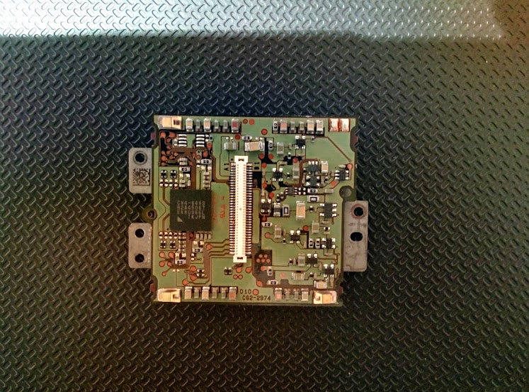
Gina, this might be a bit cheeky to ask, but seeing as you have a number of 1100D sensors in various states of operation, is there any chance you could take one of the dead ones and remove the sensor package from the PCB and post a photograph of the underside of the PCB. It would be interesting to see what's on the other side of the PCB that needs isolating from the cold finger. At the moment all I can see is the row of pins from one if the ICs, but it would be useful to know if there is any more critical circuitry under there!
Good luck with the potting epoxy!
-
OK - yer tis
 In case of confusion with my earlier postes, the RHS of this photo was at the top when I was heating the cover glass.
That does look quite precarious! Any more use of the torch might fry those gold wires if you wave it over the wrong part of the sensor

Also, not sure why your glass keeps cracking. I can only guess it's due to the heat being applied too quickly. What setting did you have the torch on? I had mine set very, very low to the point where it was almost getting a yellow flame.
-
Can you post a picture of the sensor? Might stimulate some ideas?
-
Sounds like it's going better this morning. Good luck getting the last piece off.
-
Yip! I was hoping it would melt around 120-130C. Not a chance as it turned out
-
Thank you Russel

I think I'll have another go but with a lot less cooling. I thought the thermal gradient would help with the glass removal but it didn't - I think it may have caused the glass to crack. Last time I tried this I just had the cold finger attached to a large heat sink - no active cooling.
Did the sensor work after you "cooked" it?
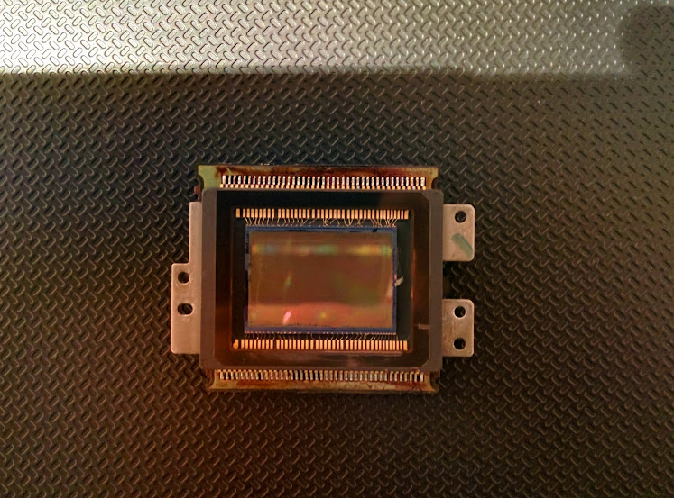
I used a dead sensor for this experiment. Here's a couple pictures of the front and back, if this had been a working sensor I'm not sure if it would still have been working after the cooking:
Russell
-
Bad luck Gina, maybe it had something to do with the thermal gradient as you say. I did both my sensors like the one I did in the video. Both worked OK and the glass came off in one piece on both.
Also, I did a little experiment today to see if I could re-set the epoxy that was left on the sensor package back to the cover glass using heat. I put it in the oven and took it up in temperature slowly from ambient to 250C. Epoxy didn't melt and all that happened was the board started decomposing. That's that idea ruled out now!
-
I now have a rig set up for removing the cover glass. I have arranged cooling of the sensor using the cold finger, TEC and CPU cooler with the sensor assembly with CF held onto the TEC etc. with wire. (Elastic bands are unsuitable with a blow lamp around
). The cooler is placed on the copper box from the 450D project to raise it off the table. The cover glass is tipped slightly forward of vertical to help it fall away from the gold wires.My heart will be in my mouth shortly
Slow and steady wins the race
Here's my video again for some encouragement.
-
 2
2
-
-
Hi
Interesting piece of software. Was wondering which version you have? Can it be used like ccdinspector?
Cheers
Louise
I just downloaded the free trial and once it expired, it was still useful to some degree. I'm not familiar with ccdinspector, so couldn't say.
-
I intend to debayer half the sensor area too - with an 1100D sensor. I will also provide and area where just the micro lenses are removed. Then for testing I will use white light for one test with diffuser over lens to provide a flat. I propose to repeat this test with an Ha filter in the light path and again with SII and OIII filters. I will then see if I can take the various image areas and select a few pixels from each and make a composite image with these adjacent to each other. The comparison of untouched sensor with the CFA and micro lens removed areas will be the most interesting. It would be nice if I could find a way to actually measure the image brightness for these areas.
Oh, and flats taken before any debayering to confirm that the sensor area that will be debayered is actually the same sensitivity as the other side.
Sounds good Gina. I used a program called RawDigger to measure the brightness of the pixels.
Do you think you could also have an area that has the antireflective coating removed as well? So you would have:
1. Original
2. Microlenses removed
3. Microlenses and CFA removed
3. Microlenses, CFA and antireflective layer removed
Or maybe that's too much of a stretch?
-
An excellent test and good analysis!
I would summarise those results as follows:
1) Losing the microlenses has reduced the sensitivity of the sensor by a factor of approx 2.
2) Removing the colour filter array has increased the sensitivity of the sensor by allowing every pixel to receive all wavelengths.
3) For red (and blue) wavelengths, debayering allows the sensor to capture approximately twice as many photons as previously (4x as many pixels are each receiving half the previous signal). This must be a good thing, especially for Ha and SII narrowband imaging. Also, since every pixel is receiving signal, the resolution of the image is increased (because interpolation between coloured pixels is no longer required).
4) For green wavelengths, debayering does not make any difference to the number of photons captured (twice as many pixels are each receiving half the previous signal) but it does improve the resolution of detail.
Overall, debayering does allow more photons to be captured (depending on wavelength) and definitely improves resolution. The results would be even better if the microlenses had not been lost.
Mark
I think we also need to acknowledge that the increase in resolution comes at a cost of reducing sensitivity by 50%.
-
But not all photosites will collect for example Ha during a real exposure of a target, or you would get a completely uniform red block as image. No?
So I don't think it's that absolute. At least that is how I interpret all this.
Otherwise all sensor QE graphs would show a 75% higher QE in red band for Mono compared to OSC.
Some sensors QE graphs don't show any difference in the red band at all! Like the KAI 11002.
I stand fully corrected if I'm wrong in the end, when real imaging tests of a Ha region gets imaged 4 times as fast with a debayered DSLR than a normal fully astro modified DSLR.
Proof will be in the pudding as they say.
Because there are 2 things going on when we debayer we should look at them individually. Firstly, reduction in QE by removing the microlenses. This, as stated, was measured to be 50%. Next, is the increase in resolution, for Ha and SII, from 1 in 4 pixels to 4 in 4. Now we are gathering light at 4 times the number of photosites but it's spread over 4 times the area. Therefore, if we take the resolution gain, we have to accept the reduction in sensitivity and increased exposure durations. But, if we combine the signal from the 4 pixels into one, we're back at the previous resolution but with twice the signal (remembering removing microlenses costs us 50%).
I'm not sure how the QE charts are prepared, but looking at them I assume it's based per pixel and not the sensor as a whole, otherwise why is the green QE the same as the red and blue but it has double the number of photosites so should gather more light! If my assumption is the case, then you wouldn't see a 400% (not sure why you said 75%?) gain for mono in the red band.
So, imaging in Ha with my debayered sensor should be twice as fast (remembering removing microlenses costs us 50%). But as you say, the proof will be in the pudding
(But i'm not sure how you world quantitatively evaluate those results?) -
We should be able to measure actual losses due to removal of the microlens if someone can take a test image indoors, remove just the microlens layer but not the cfa which is easy enough and take an image of the same object. Then compare red and blue values.
Light conditions would need to be identical though.
This test would remove the cfa from the equation.
I believe the losses were worked out to be 50%, based on the tests I did here:
http://stargazerslounge.com/topic/166334-debayering-a-dslrs-bayer-matrix/page-81#entry2308747
-
So while, after the debayering, you utilize all pixels when for example using a Ha filter, you will get a higher resolution, but due to the decreased QE / sensitivity, your imaging time (total integration time?) will NOT be faster than before the debayering. It will be the same or even longer.
My results don't agree with your conclusion. Removing the microlenses halved the sensitivity of the photosite, but debayering quadrupled the number of photosites sensitive to Ha and SII. The net effect is double the sensitivity of the sensor which would halve your imaging time.
-
Ah, yes, you must be right as it's absolute QE. For my own interest, I was thinking of just doing a simple, subjective comparison. Two different cameras but with the same lens and same scene and with same manual exposure and ISO. It's surely the result that counts
. I don't have any narrowband filters at the mo. I thought I'd do some short daytime exposures and some long astro exposures. I could simply desaturate the colour images and just compare side by side. I'll think about that a bit and I don't have the debayered camera yet. Hopefully it won't be much longer!Cheers
Louise
Edit: of course, it will be cloudy when I get it!
The trouble I see with that approach is you have no control over the scene which will be constantly changing. And that will have a significant effect on your image which could give misleading results.
I have debayered only half my sensor, so when I get the time to do some real world tests, I'll be able to do a direct comparison that will be able to negate the effects of the changing scene.
-
Hi again
Yeah, that's what I was thinking. Makes it hard to do 'before' and 'after' comparisons. Also, the green region in colour sensor graphs are the response of two pixels rather than just one - Oh, I think someone's already said that!
I think if the debayered version performs reasonably well then that's what you'd hope for and can be happy
Cheers
Louise
I think the charts are for only 1 green pixel, otherwise I would expect the QE of the green to be much higher than the R or B, but instead, the peak is roughly the same.
You should be able to do before and after comparisons with the narrowband light. Since you know that 100% of the incoming light is passing through the OSC filter, therefore you can make a direct comparison with the debayered sensor and evaluate the impact of debayering on a pixel by pixel case.
But as you say, if you're happy with the results then that's really what matters.
-
Hi
If I'm reading that right, when using the original sensor with say light via Sii, which is just a narrow band of red light, then the responses from G, G2 and B pixels are really colour 'noise' since ideally you'd want the G, G2 and B pixels to be 0?
Cheers
Louise
Sort of. If you look at QE charts of OSC sensors, you'll see the R, G & B pixels overlap each other. Thus, the G and B pixels are still capturing some of the Red SII light. It's not like mono sensors with RGB filters where you get a sharp cut off between the colour bands.
-
I was going by figures and graphs posted above but once I get a part debayered 1100D sensor I shall be able to do some tests. Then we shall see
Someone else could well beat me to it though Indeed
Here are the results from my tests using Ha, OIII and SII filters. You can see that from my sensor, removing the microlenses roughly halved the sensitivity of the photosites. But you can also see that, since all photosites on the debayered side are sensitive to the filtered light, the sensitivity of the sensor improves by 75-110% for SII & Ha (ignoring signal recorded in the B & G regions). But the results from the OIII are a bit more interesting. This showed no improvement in the sensitivity of the sensor after debayering (ignoring signal recorded in the B & R regions). Also, if you could use the signal from the B pixels, the debayering process actually makes the sensor only 75% as sensitive as the original with microlenses.
Here's the table of results:

Here are the RAW files if anyone is interested
https://www.dropbox.com/s/l0ctwa7ve17zqky/IMG_5508_Ha_7nm.CR2
https://www.dropbox.com/s/pdv66522z911rxc/IMG_5523_SII_8nm.CR2
https://www.dropbox.com/s/vgj7t4uz57w98oq/IMG_5510_OIII_8.5nm.CR2


Debayering a DSLR's Bayer matrix.
in DIY Astronomer
Posted
A rectangular piece of plastic wrapped in cling film might work?