


russellhq
-
Posts
1,432 -
Joined
-
Last visited
Content Type
Profiles
Forums
Gallery
Events
Blogs
Posts posted by russellhq
-
-
The Odroid xu4 also seems to get good recommendations as an alternative to a Pi for NAS applications (which I guess is similar to high data capture of planetary imaging)
-
 1
1
-
 1
1
-
-
22 minutes ago, Gina said:
Hmmm... Been through the forum list and it seems to "fall between two stools" - Imaging Equipment. So it falls within the Equipment group but not into any forum within this group. Guess I'll put it in this forum (Imaging Discussion) as another thread then admin/mod could move it if they think it belongs somewhere else.
Maybe the admins could create a section titled "Gina's Corner" where you can put all your threads in one place. Would be an interesting place

-
1
-
-
14 minutes ago, Gina said:
Processed Simeis 147 Ha in BPP then auto-stretched and cleaned up the background with DBE. Screenshot of PixInsight edited in GIMP with levels.

What's the lighter area at the bottom edge of the frame, left hand side? Looks like somethings not gone right with the calibration unless it's nebulosity!
-
1
-
-
Gina, did the camera come with it's own capture software and have you tried taking bias frames with that? In my experience, using 3rd party software can sometimes lead to capture issues.
That said, the 1ms bias looks more like what would be expected. What temperature was this captured at?
-
Gina, looking at your bias frames, do you think it's possible you're getting a thermal gradient across the sensor? I mean it might be possible if you are running the camera constantly for hundreds of frames at a time? I only say this because the pattern doesn't look like bias noise but more like dark noise. And if that is the case, it will not correct your light frames but make them worse!
Might be worth adding a couple seconds pause in your imaging sequence between captures?
-
13 hours ago, GTom said:
Everybody has a different budget, approach and goals in this hobby. Anyway, lots of satisfied people are using self-modded "color" DSLR-s budgeting them at their normal photo market value. I am actually reviving my astro-hobby after several years of "absence" and need a bit of a guidance.
I have a bit of a budget on an airline-portable setup now, but want to spend it wisely.For me, time is very precious, those tens of hours of exposures one often see on astrobin, would take years in my case even for circumpolar objects. Boosting camera efficiency by a factor of 2, not to mention more, would bring me much closer to the result. As I understood, B&W conversion
in theory (and from the real life samples) should bring 1EV advantage - this is like taking a 130mm APO instead of my current 90/600! Going forward I was curious if there is a meaningful second step, like 2+EV advantage by using a dedicated astro camera as the ZWO ASI.Speaking of price, one doesn't necessarily need the "top dog" asi1600mm, there are solutions at 1/2price with 8mm diameter - which might be perfectly fine for smaller objects.
Some pretty impressive work has been achieved with a standard DSLR by Scott Rosen http://www.astronomersdoitinthedark.com
I think the key to Scott's success is dark skies: they make everything better ?
-
I wonder if there is the need to run the planetarium software on the mini pc? Seems like a lot of resource just to tell the scope where to point.
6 hours ago, Gina said:Put the mini PC box out in the observatory on the pier and powered it up from the mains with supplied PSU (I'll run it of the obsy main DC supply later). Tried the WiFi but it was a bit intermittent so connected the Cat 6 cable and running wired - that works fine. Then I tried the astro stuff. Found I'd forgotten to install CdC so I did that and it runs. Runs and displays the sky chart but couldn't get it to connect to the mount either directly directly or via POTH Hub
 I checked in Device Manager and found the USB to serial adapter on Com 4. Put that in the ASCOM settings but no joy.
Then I tried SharpCap and tried to connect to the ASI1600MM-Cool but it didn't find the camera
I wonder if this is a Windows 10 problem. Have to say I'm finding Win 10 more disagreeable than other versions
-
44 minutes ago, Gina said:
Opinions seem to vary from no to yes with only for flats in between. I'm still reading various info on Google...
Take a set of cold ones then a set of room temperature, and compare the 2. Probably quicker than googling for consensus
")
-
1
-
-
19 minutes ago, Gina said:
Did forget something - filters change the optical path length but I can never remember whether it's more or less and however I work it out I get it wrong! Astrodon filters are 3mm thick and change the focus be 1mm. Maybe that will not affect things for this size of sensor. If it means it moves the focus further away I could turn an extra mm onto the camera ring for the FW.
From what I've read, they add half their thickness to the optical path i.e. increase the overall focal length
-
1
-
-
11 hours ago, tekkydave said:
Thanks, I'll look into that. I bought the xbee a while back out of curiosity so decided to do something with it. They are a bit pricey though.
I don't know what an xbee is but the esp8266 modules I looked at were only a couple of pounds plus postage.
-
1
-
-
Dave, for wireless control, have you looked into the ESP8266 module? It's a dirt cheap serial WiFi module that runs Arduino IDE code.
Here's an example of one being used to control a stepper motor;
http://www.instructables.com/id/Running-a-Stepper-Motor-from-an-Adafruit-HUZZAH-ES/
-
1
-
-
I was reading this the other day and think it might be a good contender for protecting the gold wires:
http://www.designworldonline.com/enhance-electronic-performance-with-epoxy-compounds/
It's an epoxy specially designed for the task:
- "epoxy based “glob top” encapsulants protect and support bare die and their wire bonds in chip-on-board (COB) assemblies"
-"Specifically formulated to be thixotropic, glob tops flow smoothly in response to stress applied during application, but rapidly increase in viscosity."
-"this allows them to easily cover the chip and fill narrow gaps between wires without damaging delicate parts, while preventing them from flowing beyond the desired area."
Might cut down the number of dead sensors

-
2
-
-
Aluminiumwelder, I can't help thinking that your method would work better if there was an aluminium plate attached to the bottom of the tube to increase the heat transfer area.
-
I'm not sure if you found this video in your search, but this is a video I took showing how I removed the glass. I tried this with 2 sensors, worked both times without breaking the glass, sensors were also functional afterwards:
-
There's just one faulty 1100D on ebay which I'm bidding on but there's still days left and the bids are shooting up!
That'll be the one with the faulty shutter.
I've seen the not working ones going for around £85 with the odd one at £50-60. The lower price being nearer what I'm willing to pay!
-
1
-
-
Dare I say it? I'm considering having another go at this
 Proper astronomical cameras are also an astronomical price and I just haven't got enough for the astro projects I'm working on and there's no way I can afford to buy any more. I have to share cameras between imaging rigs. I know I'm lucky to have what I've got but unfortunately I'm greedy. I'm also totally mad and feel the need to do things "no one has done before" or at least very few. Add to that the feeling of never wanting to be defeated in anything I do and there you have it!
Don't do it! You might encourage me to start again!!
:DI've got a working sensor from an 1100D with half the CFA cleaned off. I was using it for comparison tests but I've managed to kill all my working bodies. I've been casually watching ebay for cheap bodies but haven't made the plunge!
-
Ok, I'm happy to inform you guys that I have a fully working and exceptionally flat field full frame Nikon D800am (astromono;) on my desk. Flat field because the sensor is absolutely flawless.
And in additionally there is the same type D600am, yep I'm using that "am" on both of them to create confusion to model D810a

Process was very difficult and I struggled with the cover glass removal even though the micro CNC was used. I found out that that there really is no guarantee with that method either and it resulted one dead D800 sensor
 But the other one is success
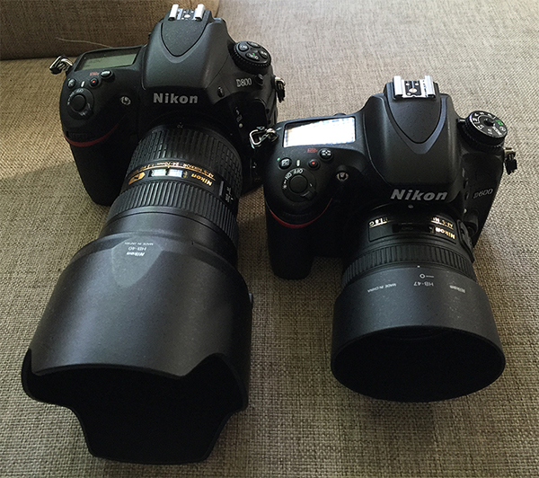
Left reads D800 and right one D600
Excellent work!!!
What process did you use to remove the CFA from the sensor?
-
The sensor looks very clean, shame it didn't work. Maybe it's worth taking apart and re-assembling again if you haven't already done that.
If you are going to try again, maybe try only a small area in the centre of the sensor. That should confirm one way or another if the soda is too abrasive I should think.
-
3
-
-
Tried with / without quotes earlier but will have another try
Still get same error message, like it can't find the path
If I put the qoutes in it removes them and puts in single ones when it runs ?
Dave
You're missing a \ in this post. Look at the path name between x86 and ASCOM, there should be a \ in there: i.e. (x86)\ASCOM
Hope that helps.
-
I wish there was more standard terminology! No, you don't rotate the camera in the focuser, there may not even be a focuser. The camera stays rigid with respect to the mount. Now, if I say "rotate the mount", somebody might think that I mean change the direction of the polar axis to the left or right. That is what's making writing the instructions a headache!
I know what you mean. I had trouble just phrasing the question!
-
Sorry, another question: When you talk about taking a portrait and landscape orientated image, is the intention to achieve this by rotating the mount or rotating the camera in the focuser between shots? It would be slightly cumbersome if it was the latter.
-
The mount (or RA or polar) axis!
After a rough polar alignment, I set the camera somewhere close to declination 90 so I can see Polaris in the field of view. Keeping the camera fixed to the mount, I slew in RA by a large angle (40 degrees say) and watch where Polaris goes. If it goes off the FOV, the RA axis is not close to Polaris. So I adjust the polar alignment, bring Polaris back into the FOV and try again (the details of this iteration need to be worked out). Once it's set so that Polaris stays in FOV after a large RA slew, we are good to fine-tune the polar alignment by PhotoPolarAlign. The first two images give us the position, in pixel coordinates, of the RA axis (the red cross). I take the first image at an RA position so that the sensor is taking a picture of the sky in "portrait mode" and the second image in "landscape mode", with the long side of the sensor horizontal. The plate solving tells me where the NCP is (allowing for precession since 2000), in pixel coordinates and what the scale is. Now that the camera is horizontal, x and y pixel offsets translate directly into instructions to move the mount RA axis up-down or right-left by so many arcminutes. After I adjust the polar alignment, I take another image and check for improvement. The RA axis pixel coordinates have not changed, only the NCP pixel coordinates move. With practice, it should take only 3-4 iterations to get it close enough (whatever close enough is for your imaging needs).
Is the aim here simply to find the RA axis in the image and the NCP and get the 2 to overlap?
-
Daft question, but does this align the optical axis or the mount axis with the NCP?
-
Will this be better than the polar align tool in eqmod?
Sent from my Vodafone Smart 4 turbo
At least as accurate but faster would be my measure of better


DaveS's Obsy Build. First thoughts.
in DIY Observatories
Posted
Steel wool can be good for small gaps if you can keep it dry. They don't much like gnawing through the stuff.