


orfest
-
Posts
23 -
Joined
-
Last visited
Content Type
Profiles
Forums
Gallery
Events
Blogs
Posts posted by orfest
-
-
Hi,
I've been trying out astrophotography from home, where 220V socket is available with unlimited power.
I want to be taking my setup to the field next year, but I'm wondering how to power all the devices.
Current setup:
- The mount (10micron GM1000) needs 24V@3A (peak 4A). To get 24V@3A I need 12V@6A
- DSLR that can run from batteries, and I have lots of spare batteries on standby
- Raspberry Pi to control the devices, 5V@3A, equivalent to 12V@1.25A
- Dew Heater that I've just got, but never used, needs 12V@1A
I'm considering some upgrades in the near future:
- An autofocuser, 12V. Power requirements should be minimal.
- Replace DSLR with a cooled camera, 12V. I don't know what I'll get, but top models need 3A. Don't know how much of it is used by cooling, and how much is used by the sensor.
Questions:
- Is it safe to power the mount from a DC hub? My mount's manual says "Please don’t use unregulated power supplies because the output voltage of these units is not good enough to operate the mount.". I didn't find anything that says the warranty is void if not using the pre-approved power supplies.
- If I don't want to power the mount from the DC hub, how can I power the mount and the DC hub from the same battery? I saw these funny devices on Aliexpress but don't know if they are any good: https://www.aliexpress.com/item/32911966417.html
- What kind of batteries do you use to provide multiple Amperes to all the equipment all night long? Mount needs 6A (at 12V), cooled CMOS camera needs 3A, dew heater needs 1A, Pi needs 1.25A. That's 11.25A at 12V, which is 135W of power. The battery must be huge.
I saw discussions of various DC hubs here:
-
Users on 10Micron Forum responded that none of them uses the "Tripod Adapter". Will do the same.
-
Dear friends,
I've received the most awesome mount ever: 10micron GM1000, and a new tripod: Berlebach Planet.
However, I still haven't got a chance to even install the new mount on the new tripod. There was some confusion, and I received the tripod with a wrong adapter. Now I have the correct adapter, but still can't figure out how to install the mount on the tripod.
According to the manual, the mount should be installed on 3rd party tripods like this:
Tripod -> Tripod adapter -> Base adapter -> Mount
With the screws provided, I can only connect:
* Tripod -> Base adapter -> Mount
* Tripod -> Tripod adapter
* Tripod adapter -> Base adapter
but not all three together
1) If you have Berlebach Planet tripod with GM1000, please please please share a photo of how the mount is installed.
2) Also, what do you think can happen if I skip the Tripod adapter and go the path "Tripod -> Base adapter -> Mount" ignoring the official manual?
Thanks in advance!
-
[A few more photos are in the imgur album]
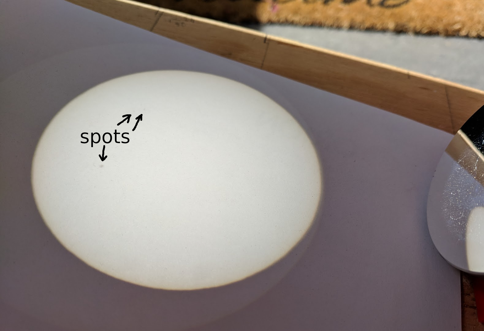
Made this telescope for observing sunspots. The Sun gets projected onto a piece of paper after bouncing from 3 mirrors inside the frame.

It's compact, light, takes only a few seconds to point at the Sun, and sketching sunspots is as easy as circling the spots on a piece of paper.
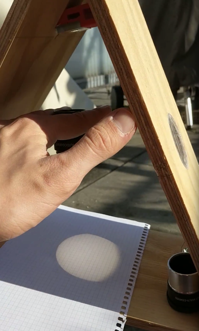
It can even project the Moon:
The design is inspired by a commerically available telescope, but I’ve done all the designing myself, just for the fun of it.
Sunspotter is full of little details that make it interesting. How do you fix the eyepiece in the exact place where it needs to be? How do you keep the lens in place and perfectly aligned?
Building the telescope was a lot of fun, I’ve learned to use a jigsaw, X-Carve and a 3D printer. The plan is to use it to complete the Astroleague Sunspotter Observing Program, but unfortunately I completed it at the minimum of a Sun cycle, and won’t see any sunspots until next year.
Telescope parameters:
- Magnification: 75x
- Size: 41cm x 41cm x 15cm
- Weight: 1kg
- Design: Keplerian
- Projection size: 75mm
Materials needed:
- Lens: Ø52mm f=750mm achromatic doublet
- Mirrors: 1, 2, 3
- Eyepiece: Baader 10mm ortho
- 1.5m² of 10mm plywood
- Wooden glue
- 5m of PLA filament
- 12 nails
- Compressed air
- Isopropyl alcohol
Tools I used:
- Jigsaw with a 30° bevel capacity
- X-Carve 1000
- 3D printer
- A laser pointer
- Clamp
Learned modelling basics in:
- LibreCAD
- Easel
- TinkerCAD
- Fusion 360
Part 1: Choosing the lens
The idea of a sunspotter is that the light goes through the lens, travels inside the telescope, bouncing from 3 mirrors, enters an eyepiece and the image gets projected on one of its sides.
The distance the light travels before entering an eyepiece is the focal length and it determines the size of the telescope.
I chose a Ø52mm f=750mm achromatic double. Observing the Sun doesn’t require a large aperture, 50mm is more than enough. I wanted a high magnification and went for the longest focal length I could find, which was 750mm. Achromatic doublet design is what people use in refractors. If it is good enough for a refractor, it’s definitely good enough for my project.
With the focal length chosen I could design the wooden parts. A drawing showed that the frame needed to have sides 30cm long, but I wasn’t sure about the placement of the mirrors and went for 31cm sides, planning to shorten the light path as needed by adjusting mirror positions.
This is the LibreCAD drawing of the layout of parts on a piece of plywood:
Part 2: Building the base
Having a drawing of the base in LibreCAD, I printed the drawing 1:1 scale on multiple A4 sheets of paper and glued them together. I transferred the drawing to a piece of cardboard and cut it out.
Applied this cardboard template to the sheet of plywood, and cut out two parts with a jigsaw.. I’m not an experienced user of jigsaw, and couldn’t manage to cut half-circles accurately enough. Even worse was that the two parts were very different. I didn’t want the frame to randomly tilt left or right when adjusting its altitude, and had to spend a lot of time with sandpaper to make the halves as similar as I could.
Glued the two large parts with three small parts in the middle. Additionally nailed the parts and the base was ready.
Part 3: Frame
The frame is simply a triangle made of three pieces, with short sides cut at a 30° angle. Most jigsaws can cut at 45°, but not at 30°. Had to buy a new jigsaw with a 30° bevel capacity.
Cut out three sides, cut short sides at a 30° angle, but didn’t put them together just yet.
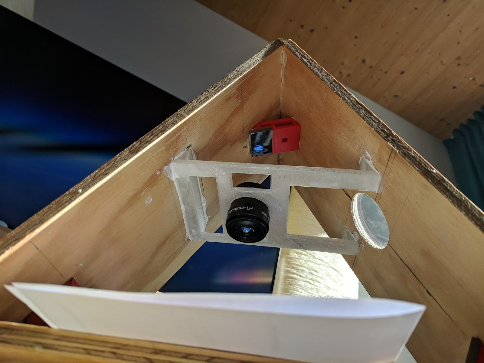
The lens needs to be perfectly aligned with the Sun-facing part of the frame, otherwise the Sun projection isn't circular but elongated.
My solution was to carve a hole with a little step as shown on the image.
The inner hole is Ø46.5mm, the outer hole is Ø50.8mm.
The outer hole is the exact size to let the lens fit, but with a little bit of friction. Had to carve several holes to find the minimal size the lens could fit in.
The step is just large enough to have enough surface for the glue to keep the lens in place, I didn't want to reduce the aperture too much.
I used an X-Carve for carving and Easel for modelling.
With all 3 sides ready, I could assemble the frame. It appeared that my 30° angle cuts were not very precise, but after some sandpapering the sides started fitting together alright. Glued the parts together and left them to dry for a day. To apply some pressure on the joints, I wound several twine loops around the frame really tight, made sure all sides fitted well together and left it to dry like that for a day.
Part 4: Mirrors
When selecting mirrors I was looking for the smallest mirror that fit the cone of light. Small mirrors are a lot easier to place, and they let me better control the length of the light path. I considered using elliptic mirrors, but they were bulky and really hard to place. All mirrors are first surface mirrors, otherwise planning their locations would be a lot more confusing.
This was my original plan of placing the mirrors:
As you can see, all the angles and distances were carefully measured, and I wanted to simply make mirror holders of those exact dimensions. This was clearly a bad idea.
I 3d-printed some parts like this:
And only later I realized that the frame angles are not exactly 60°, and that there are drops of glue along the edges that don’t let me fit the pieces deep enough in the joint between the sides.
I cut angles from all the mirror holders:
After I put the first mirror in place I realized the angles are all wrong, and that I needed to re-do the holder. Separating the mirror from the holder was a huge pain, which resulted in an accident. The mirror fell off the desk and got damaged.
Luckily, only the back side got damaged, the front side was still working:
The final designs of mirror holders looks like this:
The holes in the front surface let me apply pressure on the back of the mirror if I ever want to separate it from the holder. The recesses collect the excess glue to avoid mirror skewing when gluing them.
All other holes are simply to save the filament.
Part 5: Placing mirrors
What I learned is that you can’t plan positions of several pieces with high precision and just hope that it all comes together. I needed a feedback about the precision of mirror positions.
I used a laser pointer to verify mirror positions at each step.
In the picture you can see that the laser is firmly set in a hole in another piece of wood, with layers of isolation tape on the tip of the laser pointer to make it stable. A clamp holds the piece of wood in place, ensuring that the laser ray goes in the same direction as a solar ray would. A crosshair of black thread at the center of the lens ensures the laser goes exactly through the center of the lens.
When placing each mirror, I marked the spot where I expected the laser to end up. While gluing the mirror holder to the frame, I kept the laser as close to that spot as possible. If for some reason, the laser couldn’t hit the expected spot, I did my best with placing the mirror, and recalculated locations of the following mirrors.
I saw the first sunspots after placing all the mirrors and simply holding an eyepiece in hand.
Part 6: Eyepiece holder
I tried eyepieces of different focal length and liked the picture I got with a 10mm eyepiece the most.
An eyepiece needs to be in a very exact spot to produce a sharp image. At this point it was obvious that my frame doesn’t match the model, and that I didn’t even know what exactly was wrong with the frame. I didn’t want to rely on the model and moved forward with trial-and-error.
I printed several parts to hold the eyepiece, with different eyepiece locations:
The part in the photo was a total disaster. It needed quite a lot of filament, at the same didn’t have enough surface area to be glued to the frame, and not enough surface area to hold the eyepiece firmly.
The next iteration was a lot better:
This part has a lot more surface area, and needs less filament to be printed. I intentionally printed the hole for the eyepiece too small, and had to sandpaper it a little bit, to make the eyepiece stay firmly fixed.
Adjusting the focus is done by sliding the eyepiece up and down until the Sun becomes a circle with well defined borders.
Part 7: Dust
All optical parts should be kept clean. Dust on the mirrors and the lens will make the image darker. Dust on the eyepiece will show up as artifacts on the projected image. Unlike sunspots, the artifacts will not move with the Sun. To clean the eyepiece I used compressed air. To clean the mirrors I used isopropyl alcohol.
Part 8: Fire safety
Don’t leave devices with magnifying lenses lying around. Once the Sun happened to be in such a spot that its light went right through the lens, burning through the cap of the eyepiece. Luckily, nobody was hurt and no other damage was done.
Part 9: Future work
Build quality of the base is very poor. The frame tilts sideways when adjusting its altitude despite all my efforts. I’d like to build a new base, but leave all the work to the machines. I already have a model for an X-Carve to make both base parts, compatible with my current frame:
A notch along the edge of the half-circle should eliminate the tilt. The precision of the machining should make the base very stable. Maybe next year, when sunspots become a common daily sight, I’ll get to this project.
Thank you for reading this far!
I hope you enjoyed it.
-
 16
16
-
I was looking for a new DIY project for myself and found SID detection. This looks interesting and easy except for the preamp part.
Is it correct that preamps for VLF are not generally available and have to be DIY?
What should be the frequency range of the preamp?
I found some preamp designs for wide range, and some designs for a narrow range of 8-9kHz. Wiki says that transmitters in Europe use frequency that is at least 11.9kHz.
What frequency range should a sid-targeted preamp have? What are people doing with the 8-9kHz frequency range? Which preamp design would you recommend for someone with a very basic electronics knowledge?
Thank you!


Power for the mount and for all the devices
in Discussions - Mounts
Posted
Thanks for the link, haven't seen it before.
The largest model has only one DC output though. I'd like at least 2 DC outputs. Converting DC->AC->DC is wasting power.
I have a dummy battery with an AC plug. Good idea to get the one with the USB plug too. Thanks!