


MattGoo
-
Posts
586 -
Joined
-
Last visited
Content Type
Profiles
Forums
Gallery
Events
Blogs
Posts posted by MattGoo
-
-
Yes, it's been fine, no problems with powering my DSLR.
Only improvements could be to use a non-illuminated switch (it gave off too much light!) and maybe put in a voltmeter to display the output voltage.
-
I have a Skywatcher EQ6 mount, so the following is applicable to that. Most other mounts can be attached in a similar way to this type of pier design.Materials for pier adapter (retail):
- M12 Stainless Steel A2 Threaded Bar (1m) x1 £ 6.62 Toolstation http://www.toolstation.com/shop/p37920
- M12 Fastener x1 £ 4.50 Ebay http://www.ebay.co.uk/itm/221225381173
- EQ6 Adapter plate x1 £79.95 Altair Astro http://www.altairastro.com/pier-adapter-skywatcher-celestron-ioptron-multi-mount.html
- TOTAL £91.07
Materials for pier adapter (locally sourced):- M12 Stainless Steel A2 Threaded Bar (1m) x1 £ 6.62 Toolstation http://www.toolstation.com/shop/p37920
- M12 Fastener x1 £ 4.50 Ebay http://www.ebay.co.uk/itm/221225381173
- EQ6 Adapter plate x1 £--.-- Society member
- M10 Stainless Steel Socket Head Bolts (80mm) x4 £ 3.53 Ebay http://www.ebay.co.uk/itm/150846401601
- TOTAL £14.65
One engineering member of our society was able to fabricate a EQ6 adapter plate from aluminium for me, taking the measurements/profile from my existing EQ6 tripod head. This was a substansial cost saving over the ones available from the likes of AltairAstro which are approx £80, but meant I needed to purchase the 4x M10 socket head bolts, which are normally included in the retail versions.Another option is to use a car brake disc.Tools:- Pencil
- Drill
- Masonry Drill Bits (5mm, 10mm, 12mm)
- Spanners
- Saw suitable for metal
- Compass
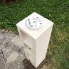
Adapting for EQ6 use:- Find the centre of the top of the block
- Use a compass to find North and mark the direction
- Place your adapter plate on top, align the peg with North and mark the required holes
- Drill through with the 5mm drill bit, followed by the 10mm drill bit. (My EQ6 needs a 12mm hole in the centre)
- Attach the adapter plate using the M10 socket head bolts and washers/nuts
- Test fit the mount on top
- Cut down the M12 threaded bar to a suitable length so you can safely secure the mount with the M12 fastener
- When skies allow polar align & enjoy using

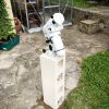
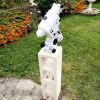 I shall be powering the mount with a powertank for the initial period. Another project is making the nearby shed into a sort of warm-room, with a semi-permanent mains powered 12v feed and usb connections out to the pier. I may write this up in another thread in the future.
-
 6
6
-
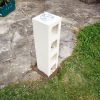
Background:Even though I'd really like one, it's not entirely practical or financially viable at the moment for me to have a permanent observatory in my garden.I therefore thought the next best thing is to build a pier - which should offer superior stability than a tripod and not take up much room.This idea was run past the wife and surprisingly approved without much fuss. When not in astronomical use it was agreed that the pier will be topped with a sundial in order to make it blend in a bit better.Since I was looking for a low cost option, I've taken the inspiration for the build from the piers at Todmorden Observatory, which I know a few other SGL members have also implemented.Materials for pier:
- M10 Stainless Steel A2 Threaded Bar (1m) x2 £10.46 Toolstation http://www.toolstation.com/shop/p79966
- M10 Stainless Steel A2 Dome nuts x8 £ 1.95 Ebay http://www.ebay.co.uk/itm/160881328576
- M10 Stainless Steel A2 Nuts x12 £ 4.49 Ebay http://www.ebay.co.uk/itm/181036635594
- M10 Stainless Steel A2 Washers x16 £ 2.69 Ebay http://www.ebay.co.uk/itm/360543852606
- 440mm x 215mm x 215mm Hollow Concrete Block 7N x2 £ 3.30 MKM.B.S. https://www.mkmbs.co.uk/prodb004313-440mm-x-215mm-x-215mm-hollow-concrete-block-7n/
- Postcrete 20kg x3 £17.97 Wickes http://www.wickes.co.uk/Blue-Circle-Postcrete-20kg/p/221100
- Wood off cut (approx 20cm x 20cm) x1 £ 0.00
- Masonry Paint x1 £ 0.00
- TOTAL £40.86
Tools:- Pencil
- Ruler
- Spirit Level
- Drill
- Masonry Drill Bits (5mm, 10mm)
- Wood Drill bit (10mm)
- Spanners
- Spade/Trowel
- Saw suitable for metal
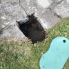
Construction Instructions:- Select a suitable site in your garden
- Dig a hole approx (30cm x 30cm square) x 40cm deep
- Cut the M10 threaded bar into 4x 33cm and 4x 10.5cm lengths
- Bend the M10 threaded bar 33cm lengths at right angles approx 8cm from one end (may need to heat them up to do this)
- Drill 4 holes into one of the concrete blocks using the 5mm drill bit, then go through again with the 10mm bit
- Place the other block on top and mark through the holes with a pencil, then drill the second block
- Use the 4x 10.5cm lengths of M10 threaded bar to attach the two blocks together using washers, nuts and the dome nuts on top
- Drill 4 holes in the base of one block
- Put an off cut of wood on the block and mark through the holes with the pencil
- Drill the holes in the wood
- Attach the 4x 33cm lengths of M10 threaded bar using nuts. This is only temporary, since this is effectively a 'former' in order to ensure that the bars line up with your block holes when they've been set in the concrete
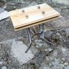
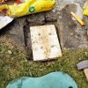
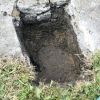
- Mix most of the concrete and pour into the hole
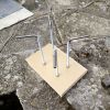
- Insert the 'former' ensuring that the underside nuts are not submerged, that approx 50mm of bar is above the concrete, and most importantly the 'former' is level
- Add more concrete if necssary & tamp down to make the top smooth
- Wait until the concrete is set & remove the wooden 'former'
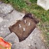
- Smooth out any unevenness in the concrete, ensure it is approx level and that the block fits onto the exposed threaded bars
- Add a small amount of concrete & place the block on top, adding more concrete around the sides as necessary
- Make sure the block is as level as possible
- Wait until the concrete is set and fix it into position using washers and dome nuts
- Paint the whole thing
Other notes:You could use cheaper zinc plated threaded bar and nuts/washers, I selected A2 stainless steel for longevity and anti-rusting.Stainless steel comes in A2 and A4. A4 is generally more expensive and is mainly for marine use.Another option for the base is bolting it to some freestanding paving slabsAnother option for attaching the blocks and base together is using specialist glue-
8
-
I've recently made myself a 12v to 7.4v battery conversion for my Canon 1000D DSLR Camera. This allows you to power it using a 12v source such as a Skywatcher Powertank/Leisure battery, and ensures there's no need for battery swaps mid-imaging run. If you buy a pre-made one then these are ~£40 from Astronomiser etc.Parts, Tools and Instructions are detailed below.Note: I've put Maplin codes, links and prices for some of the parts for reference, but they can probably be obtained elsewhere cheaper. e.g. eBay, Farnell, RS Components etc.Note 2: This is a guide only and I take no responsibility for people breaking their camera!Parts List:
- Velleman K1823 1A PSU (Maplin VE58N) £9.99
- Plastic Enclosure 75x51x25 (Maplin KC92A) £2.99
- 12v Switch (Maplin N84JZ) £1.99
- 3mm 12v Red LED (Maplin CJ66W) £0.74
- 3mm LED holder (Maplin N85AX) £1.34
- 20mm fuseholder (Maplin CT90X) £1.05
- 20mm fuse 1A (Maplin GJ90X) £0.21
- TO220 Heatsink (Maplin KU50E) £1.14
- Canon 1000D LP-E5 Battery (eBay) £2.19
- 12v Cigarette Lighter Plug & Lead (eBay) £2.75
- Wire ~£0
- Zip ties ~£0
- TOTAL: £24.39
Tools:- Soldering iron
- Solder
- Glue gun
- Drill
- Stanley knife
- Wirecutters
- Small philips screwdriver
- Multimeter
Instructions:- Open K1823 kit and complete using enclosed instructions, apart from lying the large capacitor down on its side - so it fits into the case.
- Place heatsink onto TM317, will have to bend the component back slightly so it fits in the case.
- Drill one hole in either end of the plastic enclosure for wires in & out.
- Make holes in enclosure lid for led holder, fuse holder and switch.
- Fit items into lid.
- Cut end off cig plug.
- Measure & cut wires, solder up according to wiring diagram.
- Carefully open LP-E5 battery case & remove battery, but retain contacts. (Can cut down small pcb just to leave contacts, if easier)
- Make a small hole in the battery case for wire to come out of.
- Solder up output wires from K1823 to contacts inside battery case.
- Check everything including all soldered joints.
- Insert fuse into fuse holder.
- Insert cig plug into a 12v source (e.g. Powertank).
- Use multimeter to check output voltage.
- Adjust potentiometer on K1823 board to get correct 7.4v.
- Switch everything off.
- Glue K1823 board into enclosure.
- Fit tie-wraps both sides of wires coming out of enclosure for strain relief.
- Glue battery case back together.
- Switch everything back on & re-check output voltage.
- Screw lid onto enclosure.
- If ok, then insert battery into camera and turn on.


-
5
-
 1
1
-
Great stuff. Decided not to make one from cardboard and have ordered a 5" wooden hoop like you, plus some nylon screws to avoid scratching the OTA.
Now to be patient whilst they turn up.
Maybe I'll try and make a mini-one for my 8x50 Finderscope...
-
Hello,
Got an event tomorrow and I'd like to make a solar filter tonight for my Evostar 80ED (which is now due to be delivered tomorrow, arrgh!).
Can anyone measure their 80ED and tell me the exact outer diameter of the front dew shield on it?
Otherwise I'll have to make one for my StarTravel 80 and potentially waste a sheet of Baader film.
Regards
Matt
-
Nigel - I've PM'd you back.
The box was just a standard black 8x5x3cm project enclosure - any small plastic box from an electronics dealer will do - I chose this size since it's the smallest but with enough room for the 40mm fan.
You remove the rear part of the standard 9x50 Skywatcher finder and the adapter from Modern Astronomy (£29) screws in, and has a standard webcam/spc900nc fitting/thread. It says you may have to remove the locking band at the front of the finder to achieve focus.
Due to the awful UK weather over the past few weeks, I've not been able to get out and test it, so frustrating!
-
Inspired by other threads on here, I decided to modify a XBOX Live Vision webcam, since they are cheap (£4) and are proving to be relatively good.
1) First off I totally dismantled the original housing, removing everything to just leave the bare circuit board and usb wire.
2) I crushed the 4 green LEDs with small needlenose pliers.
3) I removed the IR filter.
4) Using a 8x5x3cm project box from Maplin, I cut out a hole for the camera to stick through and placed a few drilled holes to aid ventilation.
5) A small piece of breadboard was fashioned to fit in the lower section of the project box.
6) I cut the +5v/GND wires of the USB lead and soldered in the 40mm 5v fan connections.
7) The usb lead has a GND surround which needed to be removed in order to get at the inner wires, so I added a single wire back in.
8) Cut the rear of the project box to make room for the 40mm fan.
9) Screwed the webcam circuit board into the project box using the existing holes on the PCB.
10) Mounted the fan on the project box with a 40mm fan grill.
11) Cut a small hole for the usb lead to come out of.
12) Screwed the project box all together.
So there we have it, a multi-function actively-cooled XBOX Live Vision camera:
A) Operates as a normal webcam using the original lens
 Can be used as an imaging webcam using a standard Philips SPC 1.25" nosepiece adapter
C) Can be used a guidecam in the Skywatcher 9x50 finder with the adapter from Modern Astronomy.
Still waiting for this awful wet weather to go away before it gets tested in the field. Initial indoor results are positive.


Hi from West Yorkshire
in Welcome
Posted
Welcome to the forum Gary.
There are a number of local societies in the west yorkshire region that you may be interested to contact.
https://wakefieldastronomysociety.co.uk/
https://www.wyas.org.uk/
http://www.astronomyleeds.org.uk/index.php
https://huddersfieldastronomy.org/
http://bradfordastronomy.co.uk/
http://keighleyastronomicalsociety.co.uk/