


tim22
-
Posts
17 -
Joined
-
Last visited
Content Type
Profiles
Forums
Gallery
Events
Blogs
Posts posted by tim22
-
-
On 17/03/2023 at 18:51, vlaiv said:
I just examined the attached fits - and I'd direct my attention to field flattener.
There is minimal amount of tilt and I bet it is related to flattener and not focuser / sensor tilt.
How is flattener attached to the rest of the system?
Are there any spacers introduced to dial in distance, and if so, what kind and where?
Hi Vlaiv, Thanks once again for your input. It was your original suggestion about how to measure tilt using an artificial star that interested me and that I and was all set to follow up.
But - to my embarrassment - and also relief - in further investigating the apparent problem it has now been resolved. A short window of clear skies last night allowed me to try a few more things. Having already tried rotating the camera and flattener/ reducer relative to the focuser and Objective lens I thought it logical to try rotating just the objective lens relative to everything else
Anyway to cut a long story short there were a couple of mechanical issues. Firstly I had not appreciated that the carbon fibre tube of my telescope is made up of a number of screw in sections. In trying out the experiment of rotating just the objective lens I discovered that the tube was not fastened up tight. Secondly I think that you were correct to highlight the flattener/ reducer connection -- the connection to the Moonlite focuser is just a compression ring attachment and while good as these things go it probably isn't consistent enough. The third issue may possibly also be that when conditions are really very marginal - as they were when I collected my original M44 data - it is possible to get such poor star shapes that it can look like tilt without really being that - so I probably tried to conclude too much from images that were just too poor. So as you and Skipper Billy both concluded from more objective tests- things were not as bad as they seemed.
At least as far as I can judge - I am now getting performance not perfect but probably at least as good as I have any right to expect from quite an old and imperfectly matched set up. Here is a 133 x 20s image from last night (M38 region at 1.54 arcsec/ pixel) - this time with flat and dark subtracted and ABE (background subtraction) and SPCC / SCNR colour correction applied (whole image and Aberration inspector view of the edges and middle)

To answer your queries about the equipment ..
The telescope is an old WO 110 F 7.0 apochromat with a TMB -designed lens and a black carbon fibre tube. fitted with a Moonlite 2.5 " focuser.
The flattener/ 0.8X reducer is an adjustable WO FLAT3 - which although the same manufacture is not a perfect optical or physical match to this old WO telescope . The flattener has an M63 thread which in my case is connected to the 2 inch compression ring of the Moonlite focuser via an adapter (newer WO telescopes for which the flattener is designed attach directly via a screw thread). Extrapolating from the settings for very similar newer WO telescopes (F 6.9) the expected optimal backfocus distance is very close to 55 mm. This connection to the AS1294 MC camera is rigid and firmly set using ZWO spacers (48.5 mm plus 6.5 mm internal camera distance to sensor)
So you are quite right to ask about the nature of the attachment of the flattener. The 2 " moonlite compression joint is good but can not be as consistent as a screw thread connection. So I have now ordered the appropriate part from Ron at Moonlite which should help.
Thanks very much to all who contributed to this thread. I learned a great deal from you all that I did not know -- as well as some things that I should have checked anyway - like to tighten everything up!
Tim
-
 1
1
-
-
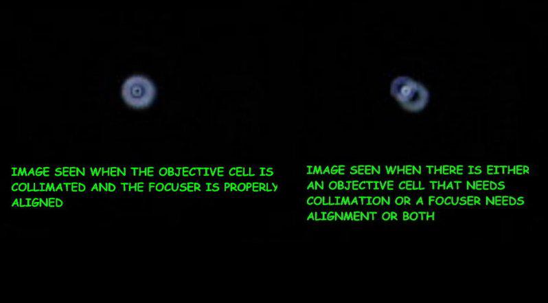
On 17/03/2023 at 18:14, John said:
The view through the cheshire (no diagonal) when it's diagonal face is illuminated reveals either objective tilt or focuser tilt as per the illustration below. If your laser eliminates the latter then the former may apply if you see the misaligned cheshire circles:
Many thanks for the explanation John. The left image is more or less what I see --actually confirming now that my system doesn't in fact have a big problem. I 'd just been making basic mistakes with tightening things up properly. At least I have learned some useful stuff from this thread though.
Tim
-
1 hour ago, windjammer said:
Looking at the pic, it is noticeable that your vignetting is off-centre. Have you tried adjusting focusser in the tube, or the focusser internals, so that vignetting is centred ? I have tried that on my scope with some success - do it in daylight with exposure and gamma turned down so all you see are the brighter regions. It has the advantage of using the camera in the image train as it would be in use - so any sagging of the train can be examined.
Simon
Thanks Simon. You could be right - I had put the assymetry down to uneven light light pollution (street lamps and house on one side). The Cheshire test that you suggested did suggest that the alignment is near dead centre of the lense - at least with no camera in there. But I will try what you suggest as a test with camera
-
4 hours ago, ollypenrice said:
The artificial star is to be found in optical workshops everywhere. The simplest is the illuminated ballbearing. Only the part of the ball closest to the lens reflects light into it, so you get a near point-source. I used it successfully to re-align the front element of a TV Genesis but, in your case, I'd start by testing the orothogonality of the focuser.
Olly
Thanks. Yes I have read about the sun reflection off of a ball-bearing method. Very clever idea. I could try that as my artificial star.
-
20 hours ago, John said:
When I'm checking refractors I use a well collimated laser to check the focuser is aligned with the the optical axis and then (after making changes to focuser tilt if they are needed) use a cheshire to check the objective tilt.
Hi John. I've used the laser and also the Cheshire to confirm that the focuser draw tube alignment to the lense is good. But I don't know how I should use the Cheshire for the objective tilt? I can see no way of adjusting objective tilt so I was anticipating putting some tilt on the focuser to straighten the image out. thanks Tim
-
3 hours ago, Skipper Billy said:
If you would like to post a single unprocessed sub in this thread I will happily run it through CCD Inspector which should identify the problem.
Many thanks for the offer Skipper Billy (I believe that you were the originator of the 2018 thread to which I alluded to above). Yes please (note --despite my reply above I am not ruling out that there is some alignment error --- there is certainly some there on more careful investigation )
Terrible images obtained in bad skies and LP between rain showers but they are what they are..
First just a cut and pastes of a Sharpcap stack - no flat applied - of M44 -- and the Aberration Inspector analysis of the same with the subjectively worst afflicted areas marked by me with a P.
Then .FIT files of a single sub and firstly also of the stack (since the SNR of a single 10s sub is so poor)
Stack_16bits_60frames_600s.fits
thanks Tim
-
15 minutes ago, windjammer said:
Have you tried the conventional cheshire-crosshairs route ? The idea is to have the lens cap on, illuminate the cheshire and look at the reflections of the crosshairs coming back from the interior objective lens surface(s). The reflections should align with the original crosshairs. Adjust focuser in the OTA tube if a primitive SW scope (like mine), or the lens cell bits if collimate-able, until reflections line up.
If you fiddle around with an eyepiece you can use your camera to view the action while you wield the spanners -makes life easier. See pic. Usual issue with a cheshire is making sure it fits properly in the focuser - no wobbles or tilts. Worth a try if you haven't done it.
Simon
Thanks Simon,
I was completely unaware of the possibility of using a Cheshire in that way. A very useful suggestion and something to try. But the thing that you really opened my eyes to was the fact that you can put a lens cap on and then look at the reflections back from the lens ! I am more used to collimating Newts and so already have a fairly well aligned Hotech laser as well.
So I just tried using the laser - which is a decent fit into the focuser - as well as the Cheshire (needed to get quite a bright light to see it) and -actually the alignment looks really quite good
So unfortunately it looks like I am back to the tilt question again - but thanks both excellent suggestions on something that I hadn't checked before.
Tim
-
Thanks David! Gosh 10 mm is a lot! That is a good suggestion that I haven't tried. It could be misalignment rather than tilt. Will try it
Tim
-
I appear to have have an issue with tilt somewhere in my Apo 4 inch refractor which is fitted with a Moonlight focuser. The issue does not appear to be sensor tilt (ASI 294MM camera) or anywhere in the optical train from the reducer/ flattener to the camera since when I rotate this entire assembly through 180 degrees realtive to the focuser the 'tilt pattern' of those sectors of the rectangular image that show elongated stars also rotates accordingly.
So - the tilt presumably arises from some slight misalignment of the object lens within the tube and/or of the focuser to the tube. I have tightened up the focuser - no evidence that there is any flex in the draw tube. The Moonlite C2.5" focuser has four (effectively 3) screws that can be used to adjust tilt by slightly shifting the spacing between two flanges. However I am a bit wary of adjusting these until I am clear exactly what I am doing and also of the fact that it will be difficult to adjust at night under stars -- constantly imaging, analysing star shape across the frame (PI Abberation inspector etc) and then adjusting again etc. And of course so few clear nights and is that how you what to spend them?
So I am very interested to know whether anyone has experience of using an artificial star for solving this sort of problem? Browsing through the SL archives I saw one (I must say of many) rather brilliant posts from @vlaiv on this particular topic in 2018 in which (if I paraphrase correctly) he suggested focusing on an artificial star lined up dead centre of the image and then -- using Sharpcap's ability to measure and map FWHM values -- track how far best focus apparently shifts as you shift the telescope to align with the four corners of the sensor. Identify the 'worst' - most shifted corner. Try first adjusting tilt to reduce the problem at this corner - then go back to the centre again and repeat etc.
I wondered whether anyone has actually tried this in practice -- or alternatively any other suggestions ?Tim
-
Many thanks folks. I was thinking about this all wrong and assuming that I could get Stellarium to work on Windows in the same way that SkySafari does on Android and INDI where you can align directly from the planetarium programme. Yes I am sure that you are right and the best way will be to use a plate solve - where I guess that the plate solve/ align function will talk to the Synscan app driver. TimH
-
Many thanks. Yes indeed I do intend to move on to that and normallly do the same with my EQ mount and platesolve within Sharpcap. However I was guessing that if I can't even align from within Stellarium then it probably won't work from within the capture software either but I'll give it a go.
Tim
-
Hi folks,
I have downloaded ASCOM, an up to date version of Stellarium, USB driver . the Synscan app and the Skywatcher ASCOM driver onto my computer and am attempting to control a SW Synscan GOTO 250mm DOB from my PC using a USB cable. It sort of works in the sense that the Synscan App controls the telescope and when I load up Stellarium I can see a reticule in the right place and can move the scope around from within Stellarium with GOTO commands. However I don't seem to have anyway of carrying out aligments i.e moving the scope to a more accurate position and then aligning so as to create a more accurate pointing model?
Does anyone know what I might have missed? Thanks for any help with this.
Tim H
-
Hi Vlaiv,
That is an interesting set of experiments. Firstly I like the idea of having a set up like that to test out optics. It is a waste of precious clear sky time to be doing that in the field. It nicely confirms what you said about the relationship between FWHM values measured in DSS / Sharpcap and SNR. Also- since it is a controlled 'lab' experiment - it takes out any potential for a greater 'guiding' contribution to FWHM at longer exposures.
I suppose that means that the higher FWHM values at bin2 are probably providing the more realistic indication of the seeing. Anyway I think that you have solved the puzzle and have certainly taught me something. Thanks again
Tim
-
Thank you both very much for those replies (I wasn't quite sure where to put the post as although I am mainly interested in the live EEA aspect and flit from target to target I do also capture like to capture some of the images bit I am not a serious imager). I use Sharpcap which allows you to do both things while live stacking.
In answer to your first point Martin I did wonder about the basis of the DSS score but, like you, guess that it must be independent of binning -- but maybe 1.6 arcsec / pixel was indeed too close to the seeing FWHM?
Vlaiv, your point about the difference in the 1x and 2X noise floor and the way that DSS calculates FWHM makes a lot of sense. Sharpcap gave similar FWHM pix estimates but it probably works in a similar way? I hadn't thought of that at all . It is a significant point of difference between 1x and 2x binned images and maybe particularly so for such short exposures?
I will have a look at Astroimage as you suggest. That is also an interesting point that you make about whether or not binning was carried out before or after debayering/ pixel interpolation. The software binning was carried out in Sharpcap and I expect that Robin Glover is aware of the potential problem that you mention but I will ask him. By visual inspection I would say that the 2x binned images do show significantly improved SNR but are not quite as sharp as 1X.
best wishes
Tim H
-
Hi folks,
This is my first post - apologies that it is such a dry and technical one 🙂 - and I was wondering if anyone could advise me where I am going wrong with the following or explain what seemed puzzling to me relating to the effect of binning on FWHM values?
Using an SW Skyliner 250 mm F4.7 (f 1200mm) goto Dobsonian with a Baader coma corrector and an ASI294 PRO MC camera (4.63uM pixels).
I tried an experiment with 3s subs (gain 200, offset 29) to photograph star clusters (M34 and M103) in order to compare the results unbinned and at 2x2 binning, At 3s there is relatively little added blurring due to Dob field movement. The 2X binned and 1X images were taken within minutes of each other (so no substantial change in seeing or drift in focus).
The image scale for my setup is (I think) ~ 0.8 arcsec per pixel unbinned and 1.6 when 2 x binned. Based on DSS scores the FWHM -pixel of 1X raw FIT files averaged about 4.2 pixel. Thus I calculated that the FWHM in arcsec was about 3.4 (~ SQR of sum of squared contributions from optics, movement and the seeing).
What puzzled me was that when I went to 2x2 binning DSS reported average FWHM- pixel scores of about 3.2 pixel where as I was expecting perhaps about 2.1 ? i.e. with 2 x 2 binning the overall FWHM in arcsec would now appear to be about 5.1 and yet, relative to 1 x1 binning nothing in the optics, field movement rate or actual seeing should have changed?
There is obviously something that I am failing to understand here and I would be very grateful for any enlightment that folk might be able to offer
(the images themselves were not bad with the 1x images looking slightly sharper but less bright than 2x binned)
best wishes
Tim H


Using an artificial star to adjust focuser tilt in a refractor?
in Imaging - Discussion
Posted
Many thanks indeed for this Skipper Billy. I think that your analysis confirms that I didn't have the problem that I thought I had. Please see my reply also to Vlaiv who made rather a similar point . Anyway it is a relief for me that my set up is not so bad - and that there is room for a bit of improvement perhaps just be tightening up all the coupling and possibly further optimising the backspacing from the reducer/ flat?
Tim