


vlaiv
-
Posts
13,241 -
Joined
-
Last visited
-
Days Won
12
Content Type
Profiles
Forums
Gallery
Events
Blogs
Posts posted by vlaiv
-
-
7 minutes ago, philhilo said:
Not sure if DSS gives me the option on selecting the value of sigma (good job I have a qualification in Lean 6 Sigma, a quality and efficiency tool so I have some idea around this even after 2 nights of 2am...….and another 2 to go 8-) ). Will check it out.

Kappa is sigma multiplier - above is two sigma range. Number of iterations is used to determine sigma and do clipping. In each iteration - all remaining values are averaged and standard deviation is calculated. Only pixel values that lie in avg +/- kappa*sigma range are "passed" to next iteration. Average value in last iteration is result of stacking for that particular pixel.
Above 2.00 and 5 settings are quite aggressive. Out of 100 subs, it will on average leave only ~68.3% samples and reduce SNR improvement from x10 to ~ x3.85 if all subs are good and without issues!
(in each turn it will throw away ~32% samples and it will do that 5 times).
Much better settings would be - 3.0 and 3. Out of 100 subs that would reduce SNR improvement from x10 to x9.955
-
 1
1
-
-
1 minute ago, philhilo said:
Very useful granular info - 16 dithered frames for the sigma kappa clipping. 200 should be sufficient be ok then.
That really depends on parameters for sigma clipping.
Not sure if people understand how to properly select them. Here is quick explanation:
This is important graph to understand when thinking about kappa value in kappa sigma clip (or just plain old sigma clip algorithm - so many names for it
 ). It is famous "68/95/99.7 rule".
When we have gaussian distribution of samples - 68.27% of all samples will fall within one standard deviation away from true value. This means that if all subs are without issues - 68.27% of them will have pixel value closer to true value than single sigma.
Going further - 95.45% of pixels will have value within 2 sigma from true value and 99.73% will have value within three sigma from true value.
What does this mean for algorithm - it means that if you want to be sure that you include as much values from your subs - you should choose kappa to be 3.0. This will ensure that almost all proper pixel values will be included and that really anomalous pixel values will be excluded.
-
In my view:
- one should dither and preferably dither at every sub. If you find it to be too much a waste of time - dither every couple of subs. In reality, it's not that much a waste of time. My dithers last 10 seconds or so. I guide with 3-4s guide cycle and it takes 3-4 exposures to complete dither. That is at most 20% or so spent on dithering even with very short exposures of 1 minute. If I use 3-4 minute exposures, that goes down to less than 10% of time. This is compensated with additional half an hour of imaging for a night of 4h of imaging - so again not such a waste of time.
- If you have good guiding and work on lower resolution - dithering is very important. On high resolutions if you guiding is not so tight - subs will be somewhat dithered "naturally". Dithering is beneficial always, even if you have perfect camera with no issues like hot pixels and such. This is because dithering "spreads around" noise from calibration subs further.
Do remember that you need to use specific algorithms for dithered subs to work the best. You won't get anything special with simple average. You will get above mentioned clusters of hot pixels. Use sigma clip stacking (sigma-kappa, or sigma reject or however it is called in your stacking software) to benefit hot pixel removal from dithering. In fact use such algorithms always when dithering.
-
1
-
-
1 minute ago, Rodd said:
Thanks. Oh well. I will remove this post as if I’d s big pointless now.
Don't remove it, I went thru the trouble of making those nice screen shots - don't want it to go to waste
-
Not real, posterisation due to processing.
If you want to know what is real / to have a good reference - there is massively detailed image of M31 online, let me find a link to it.
Due to original size of the image (69536px x 22230px and 4.3GB size) here is "zoomable" online version:
https://www.spacetelescope.org/images/heic1502a/zoomable/
Here is screen grab of core region:
There is some sort of ring like structure, but that is not what is showing in your image.
Btw, I just love that extreme resolution image - as it shows features like this:
That would no doubt be mistaken for a star but is globular cluster. Or maybe this one - Andromeda Pleiades anyone?
-
I don't think there is simple answer to that question.
Topic is rather complex and depends on the way you process your images among other things.
To see what is acceptable level of noise in particular color - we need to examine how people perceive difference in color based on how "distant" colors are in physical world.
For example - look at this chromaticity diagram with error contours:
Colors inside ellipses are roughly the same visually (same level of difference across the surface of the contour) but sizes / diameters of these error contours are not the same and depend on color itself.
It looks like we are the least sensitive in errors in green but we react strongly to errors in blue.
This suggests that noise in blue should be the least and eye can tolerate errors in green the most.
I've written above just to point out how complicated the topic is - I did not even start to consider relationship between luminance noise and chrominance noise and how do we perceive each.
Bottom line - maybe try out couple of approaches - same time spend on each of LRGB, twice more time for L than for R, G and B combined, binning of color and so on and just use the one you like the most, as there is no definitive answer of what is the best way to do it (maybe there is, but I don't think we know it yet).
-
 1
1
-
-
33 minutes ago, Samibotss said:
Is the extra stability worth it over the less accurate tracking of the EQ-5? The EQM35 has a larger payload capacity and a modular design, so unless you're speaking from experience, it seems on paper the EQM-35 would be more stable?
I'm speaking from position of limited experience with mounts - I've got Heq5 that I've heavily modded to get it to guide at 0.5" RMS.
EQ35 is hybrid of EQ5 and EQ3. It is based on EQ3 platform with RA assembly of EQ5 if I'm not mistaken (or according to EQMOD Prerequisites page found here http://eq-mod.sourceforge.net/prerequisites.html) could be that it is in fact RA from EQ6 class mount - both EQ6 and EQ35 have 180 teeth on their RA worm gear.
In any case, I'm skeptical that EQM35 has higher payload capacity than EQ5. Both are quoted differently on different websites - but most of the time it is something like 10Kg visual 7kg imaging, and I guess that is about right. However if you look at supplied counterweights you will notice that they are different - EQ35 has 2x3.4Kg while EQ5 has 2x5Kg counter weights. Larger counter weights means you can balance larger scope and it stands to reason that this means mount has higher capacity.
I think that Eq35 is more like Eq3 - meant for portability but with improved tracking / guiding performance.
On the topic of guiding - we can't say which one of these mounts will be better at guiding. On paper there should be not much of a difference between the two. Both have just a bit less than 0.3" step resolution (0.28125 for EQ35 and 0.287642 for EQ5). EQ35 has much less precision in DEC so that could be a drawback, but it won't be huge disadvantage. In reality - there is so much sample to sample variation that both can perform good or bad and be better than the other and if you want to get the most out of your mount - you will have to tune it at some point.
With a bit of luck and a bit of skill you should be able to get rather good mount out of either of the two. I still recommend EQ5 as stability is important part. If on the other hand you value portability - then choose Eq35.
-
What is your budget in the end?
I would not consider EQM-35 as an option - price difference between it and EQ5 is very small and EQ5 is going to be more stable mount.
Another a bit more expensive option, but not as expensive as Heq5, would be this:
On the other hand, if you are tight on budget but are handy and don't mind a bit of DIY, maybe get plain EQ5 type mount and motorize it yourself. Either some arduino + steppers or maybe kit conversion.
https://www.astroeq.co.uk/tutorials.php
or
You can do the same for EQ3 but EQ5 is better mount.
In the end, some people use AzGTI in EQ mode or Star Adventurer for very mobile, very low cost imaging solution.
-
I think you have a light leak.
You should not have such gradient on your dark, and there are hints of dust shadows, although, depending on type of light leak - I would not expect them to look like that.
It looks like it might be front side IR leak perhaps? If scope cover is plastic, and plastic can sometimes be transparent to IR wavelengths. This would also mean that you did not have UV/IR cut filter in place when you took your darks.
In any case - making sure you don't have a light leak would be first priority. I can't explain that brighter patch, but let's see if you have a light leak issue and if solving it solves other issues.
-
1
-
-
49 minutes ago, Rodd said:
I would disagree, my friend. I have not seen rays this pronounced before with the same optics
Maybe you did not use sensitive enough camera before on this target / star combination?
-
57 minutes ago, Rodd said:
I added the screen stretch version of the image--prior to any non linera prosessing to show you the big draeback of the ASI 1600 sensor. The bright rays emanating from teh top of the image come from the star Phecda (Y Ura Majoris). Its the star at the base of the dipper opposite where the handle attaches. These rays are coming from a star more than 2 FOVs away. I included this preprocessed image just to show the types of obstacles the ASI 1600 throws at you. Also, one can get an understanding of my sky magnitude from the screen stretch. Dealing with this while trying to establish a decent background without clipping the target is one of my most difficult tasks.
Are you implying that ASI 1600 sensor is somehow responsible for those rays? I would say it is down to optics rather than chip used to record the image.
-
Over exposure of luminance is not important - you end up with very strong stars after stretch anyway - as if they were clipped in recording.
Color on the other hand should not be over exposed, but luckily there is simple technique that one can use if they have over exposure (even if it is only star cores), shoot only a handful of short subs and replace over exposed pixels in final stack with suitable values from short stack.
-
9 hours ago, tooth_dr said:
Just to jump in here - everyone is saying they are using 1/2 the exposure duration for luminance compared to RGB? Instinctively I assumed the opposite. This may have been where I was going wrong. Unless binned 2x2 and then use the same time?
That sort of makes sense. I'll explain briefly why.
Duration of exposure (if you worry about that sort of thing - getting last bit of SNR) is related mostly to sky glow related noise. Cooled cameras nowadays have rather low dark current so that is not biggie, we often image faint stuff so shot noise of target is not dominant (and if it is - signal is already strong so your SNR is fine) that leaves sky glow noise as important bit - you want that to be larger than read noise. At that point you enter region of diminishing returns - yes, longer subs will get you better result but difference becomes marginal real fast.
RGB filters divide 400-700nm range in roughly 3 distinct equal "zones", each about 100nm wide. While L covers whole range. Sky glow can be thought of as rather uniform over that range. From that it stems that L filter will capture about x3 more signal in same amount of time as each of RGB filters. This means that it will capture Sky glow at same increased rate and consequently related noise will be larger by factor of about square root of x3 = x1.732.
To get same ratio of sky noise to read noise you should roughly expose L x1.732 = ~x2 shorter - or about half of RGB exposure.
-
1
-
1
-
-
Completely irrelevant in all aspects and most people use single exposure because it is the easiest approach - single master dark needed.
- color balance does not depend on exposure length - if you think it does - you can simply scale channels by multiplication to match what signal strength would be in equivalent exposure.
- SNR does depend on number of exposures vs exposure duration based on read noise and LP noise, and in principle you could find certain exposure length for each channel that is equivalent in some metric to other channels based on this, but that is not going to guarantee you same SNR per channel - in the end, most of SNR depends on target signal and that is different for each target. You can control how much SNR per channel you have by using different total imaging time (different number of subs of same duration) instead of sub duration.
- I've seen someone talk about color binning - it is almost the same thing with CMOS cameras and CCD cameras, or software and hardware binning. In fact if you are clever and do the math properly - you can make them be the same, but it's not really needed as difference will be small to start with. It is worth binning color and then resampling that to higher resolution of Luminance if you suffer color noise. You don't have to do it - you can do much stronger noise reduction on color channels prior to color transfer - effect will be pretty much the same. This is because we tend to perceive detail in luminance much more than in color.
-
1
-
-
5 minutes ago, Ags said:
I shot a dark SER sequence last night, but now I see Autostakkert wants a still image as a master dark file - it does not accept the SER file. Is there any way to get Autostakkert to turn my SER file into a master dark?
Otherwise I guess I have to turn the SER file into a sequence of PNGs using VLC and then stack in DSS?
Maybe it would be best to do calibration in PIPP and then run calibrated thing in Autostakkert
In any case, you can use PIPP to turn SER file into FITS sequence and then stack FITS in some other software. Make sure that you turn off all processing in PIPP and select FITS files as output.
-
Hi and welcome to SGL and yes, I believe this is related to debayering - or particularly wrong bayer matrix order used.
RGGB should be proper order, but this also depends on other things - like if software used reads frames "bottom/up" or "top/down" (don't ask - strange convention that screen space is top/down - positive Y direction is down, while file space is, like regular coordinates with positive axis going up and sometimes software developers don't pay attention to this or choose to disregard this for simplicity).
-
1
-
-
If you want to try to get that "natural" look of this nebula, here is workflow that I would suggest:
1. Make synthetic luminance - use approaches like - weighted average, or max(ha, OIII). If Ha image contains signal in all areas where OIII signal is - use Ha as luminance as it is almost always higher in SNR.
2. Use color picker to pick your blue. Closest color to OIII is something like this:
but you might want to choose a deeper blue. Once you select the color you want - check RGB ratios for it
3. Stretch Ha image but don't over do it - if you want to have distinct blue - leave center dark when you stretch - this will be your red channel
4. Stretch OIII image and apply it to RGB with channel mixer with specific ratios for blue color of your choice.
5. Combine red stretched Ha and stretched OIII colorized to blue to get color information
6. Stretch synthetic luminance and do denoising / sharpening, all the processing that you like in your image
and finally
7. transfer color from 5 to 6 for finished image
-
2
-
-
Negative / invert makes issue with color.
If you want for example to keep actual color of stars in your sketches when processing them - there is simple way of doing that.
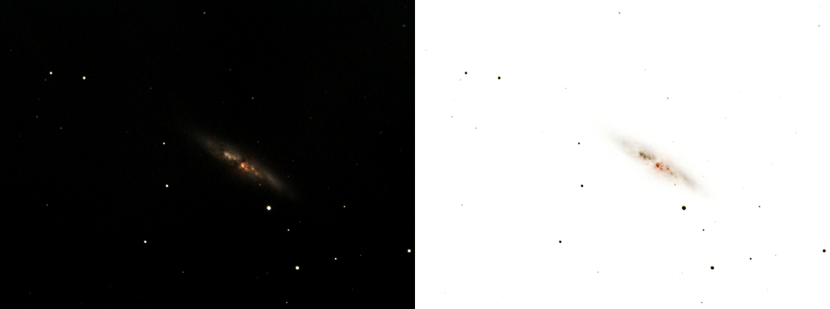
Here is example I made couple of years ago to show this effect:
Image is that of M82 - what I took with QHY5II color camera at the time (a bit of EEVA back then) and right is what it would look like if done on paper.
You can use Gimp to accomplish this (or any other program that can do color space transform). We will do it in one direction, but you can do it in opposite in the same way:
Open up image like this one:
Choose Colors / Components / Decompose and choose LAB color model.
Take L component and do Colors / Value invert and after that do Colors / Components / Recompose
This is result:
(here stars are black without color because they were saturated in original image - but in your drawing they should contain color if you draw them with appropriate color).
HTH
-
1
-
-
1 hour ago, Nikodemuzz said:
Thanks all! It seems to make sense to save the money and potential headache and go without encoders.
Now to decide on the model. Not sure if it is going to derail the topic completely to discuss it here, though. The main scope for the foreseeable future will be a 120-130mm APO, used primarily for imaging. But I don't want to be having to upgrade the mount even if I would get a bit heavier/larger scopes.
I'm sure the CEM60 would be able to handle that, so I'm not sure how much there is to gain by going to heavier mounts, such as the CEM120 or the more premium ones. One thing to consider is the fact that I will have to set up for each session in the backyard, but at least the hauling by car will be mostly in the past.
If you will be doing setup each session - limit your choices to CEM60.
I would advise CEM120 otherwise regardless of the fact that you will be using relatively light scope (less than 15Kg total), but mount head is 26Kg alone .... I'm sometimes fed up with setting up Heq5 each session
.
If you can - maybe build a pier if you have an option to leave mount on the pier when not in use (as opposed to being stored away). In this case I would say that CEM120 is still an option.
-
Non guided use - encoders
Guided - no encoders
-
2
-
-
2 hours ago, Ags said:
Ah, thanks to you I have learned something fundamental. The sky fog photons scatter randomly onto the sensor pixels, and the brighter the sky fog the more similar the totals on each pixel is, so I would be able to take a very good smooth picture of the sky fog... But the absolute difference between the totals on each pixel increases (at the square root of the total sky fog signal) so that when I "zero out" the sky fog in post processing, I only subtract the baseline from each pixel, leaving 100% of the noise component. If I was using an NB filter, the sky signal would be lower so the noise from random photon scatter would be reduced in absolute terms.
Indeed - same thing applies to other "signal" sources - target signal (good signal) and thermal signal (like sky signal - bad signal as you remove it by calibration but random component remains).
All of these are modeled like Poisson process.
-
Yes.
Primary role of NB filters is to cut sky background and associated noise. Just reducing background levels is really not important on its own - you can control that in processing by setting black point. It is associated noise that is problematic - stronger the signal - stronger the shot noise associated with it. Sky background does not contain important signal - it just contains constant signal and that is not useful - but noise associated with it is bad for image.
Short vs long exposure - if read noise of camera is dominant noise source in single exposure - you will benefit from doing longer exposures (until read noise is not strongest per single sub). Reducing noise from LP/Sky background makes read noise dominant - and that is why it is better to do longer vs shorter exposures.
If you limit yourself to having only short exposure - then NB filter vs without filter is again better - it will remove sky background associated noise, so in this case - just going with short exposures regardless - NB filters help if target emits in NB lines of the filter of course.
-
1
-
-
26 minutes ago, Grumpy Martian said:
I always thought that a polarising filter protected against UV and IR.
Am I incorrect in this belief?
Polarizing filter is selective in polarization and not wavelengths. This means it will pass some of UV and some of the IR in the same way it will pass some of the visible wavelength - depending on their polarization.
-
I think it has to do with UV rays.
Although solar filters remove a lot of light - Sun does emit a lot of light and using large scope also collects a lot of light. In the end there might be enough light left to do some damage.
Let's say that we are using 100mm scope and that normal pupil in daylight is about 1-2mm? Right? That is somewhere between x2500 to x10000 more light collected by the scope then by directly looking at the sun. Now we have Herschel wedge which leaves about 1/20th of the light (5% or so?) and ND filter - ND3 which gives 1/1000th of light - combined they give 1/20000th of the light.
That is only about 1/4 - 1/10 of what we would gather by naked eye - and looking directly at the sun. Image is magnified so it does not look as bright but same number of UV photons reach our eyes.
There are number of resources online about harmful effects of UV on eyesight.
As for Baader Continuum - it appears that Baader changed something in their manufacturing process as before their filter response curve looked like this:
There is a leak in UV part of spectrum.
So I guess it is all about avoiding cataract and other nasty things that can result from UV exposure.


Dithering about dithering
in Getting Started With Imaging
Posted
I did not want to get too technical, but here is what I find to be the most beneficial part of dithering.
People tend to use too few calibration frames. Let's for the moment just consider dark subs. Imagine we have a camera that has 3.5e of read noise (many modern cmos camera have less than that, but CCDs have more). You'll often see recommendation for 20-30 dark subs. Let's go with 25 - its easier to calculate. Stacking 25 dark subs will reduce read noise by x5 in master dark. With cooled sensors read noise is dominant type of noise in darks, so we can say that master dark is having 0.7e of noise in it (3.5e / 5).
Now imagine you have perfect guiding and there is no shift between the subs. Each sub is calibrated by first subtracting master dark, and then subs are added / averaged together. If you don't have shift between subs - same master dark will be removed from all subs for a given pixel. This means that we can "pull it in front of the brackets" - mathematically speaking.
To be very precise mathematically - it is like subtracting same value from each number in average - it is same as subtracting that number from average.
What happens is that you will stack your subs and in the end you will "add in" 0.7e of read noise back in. If you have a lot of subs (and we mostly do) - their total read noise will be small. For example, let's stack 256 light subs. They will also have 3.5e worth of read noise each, but after averaging them out, they will have 3.5 / 16 (16 being square root of 256) = 0.21875e
Now we remove our master dark and hence add 0.7e worth of read noise back in, and resulting read noise will be ~0.73338e - or almost the same as read noise of master dark!
As a contrast, let's examine case where we have perfect dither between every frame. In this case we know that no pixels from master dark will land in exact position twice and we can mathematically treat those values as linearly independent vectors - same addition applies as with regular random noise.
In this case we must calculate each sub - master dark read noise and then stack those 256 resulting calibrated subs. Every single sub will have sqrt(3.5^2+0.7^2) = ~3.56931366e of read noise. We are stacking 256 of them, so result will have x16 less noise, or ~0.22308210372e of noise.
If you don't dither and have perfect guiding read noise will be almost the same as master dark - in this case 0.7e, but if you dither perfectly, read noise of stack will be the almost the same as if you did not use master dark at all and it did not contribute anything - 0.22e
Or in another terms - just dithering in above imaginary example made our background contain x3 less noise (we did not include LP noise and other stuff - and granted it changes picture a little, but this holds - it is always better to dither because of this).