


vlaiv
-
Posts
13,002 -
Joined
-
Last visited
-
Days Won
11
Content Type
Profiles
Forums
Gallery
Events
Blogs
Posts posted by vlaiv
-
-
To further expand:
https://en.wikipedia.org/wiki/Solar_eclipse
(it has nice info on both lunar and solar apparent size depending on current orbital position and how they relate)
-
1 minute ago, AlcorAlly said:
@vlaiv sorry do you mean position A is better if there's significant source of indirect light that is in front of telescope e.g. street lamps? As in better for reducing light scatter?
As for reducing the actual aperture, you don't think that the effects of an aperture mask are more pronounced when the mask is positioned at the location where the effective aperture is defined i.e. at the objective lens?
Right. Position A - better if there is street lamp near by (although if scope is properly baffled and dew shield has mat black paint on the inside - difference will be minimal if at all visible).
No difference between two positions as far as view goes when there are no street lights involved. Sources at infinity don't really care if mask is a bit away from the lens.
This is strictly not true for very wide field use, where edge of the field stars / objects won't hit center of the lens if aperture mask is further away - but for normal use and few degrees of distance from optical axis - everything is the same (here is diagram to explain this last bit):

If incoming light rays are at very high angle and aperture mask is further away - you might end up using edge of the lens rather than center - red arrows in above diagram. For few degrees - this is generally negligible effect (you can calculate the offset - as it is sin(angle) * distance - so for 2 degrees of axis, or 4 degrees of FOV in total and 20cm of distance of aperture mask - offset would be 6.9mm from center)
-
When focused at infinity - I think there is zero difference between the two.
There might be slight difference in what you suggest - but only if you have significant source of light that is in front of telescope - but not directly - so that light is able to hit interior of dew shield.
-
 1
1
-
-
5 minutes ago, Xiga said:
So somehow, the meridian flip un-glitched the software and the cooling suddenly started working fully again, is my best guess so far!
I don't think meridian flip un-glitched the software

I'm more inclined that meridian flip un-glitched dodgy power connector for 12V to camera cooling. Without it - peltier won't work and although software might think it is cooling the camera - without power it won't.
-
2
-
-
It is very easy for an achromatic refractor to reproduce images obtained with Seestar50 - even cheap achromatic refractor.
With achromatic refractors - there is something called CA index - or index of chromatic aberration - which is a number obtained by dividing F/ratio of the lens with aperture in inches.
50mm is 2" and telescope needs to be F/10 or slower to show virtually no CA. In fact - if we take very cheap and common 80/900 refractor and put 50mm aperture mask on it - we will get F/18 instrument with 2" of aperture. I think that sharpness of such arrangement will beat seestar in terms of performance (if we speak of sharpness and contrast).
Even very fast ST80 will come very close to be color free and very sharp without any filters if we put 2" aperture mask. Most people with SkyWatcher version (not sure if other versions have this feature) can actually try this by removing small central cap of the lens cover:
-
4
-
-
I've been saying that 3d printer is probably one of highest value accessories in this hobby - for anyone with even slightest DIY ambition.
Astronomy buddy of mine just got himself a Bambu P1S and one of his first prints was M48 / M63 adapter to attach camera and reducer to focuser on his 6" RC.
He intended it for prototype only - to verify correct spacing and that he'll be able to achieve the focus, but after seeing the quality of the print (I helped a bit with modelling and slicer settings) - he now thinks he'll be just using 3d printed version.
-
3
-
-
That is a trick question, and like dear friend of mine once said - "I don't answer trick questions"
-
 2
2
-
-
26 minutes ago, pipnina said:
I only have a cursory knowledge of electrics in motors in general, but I think as a motor spins faster the magnetic back force increases which means you need yet higher voltage to move the motor. I'd guess if voltage correlates to max speed it's because of that. Holding torque I'd guess would be current based as the strength of the magnetic field is proportional to current and not voltage.
I think you are right! Same thing is mentioned in the answer that I linked.
-
1 hour ago, wimvb said:
There are low current versions and high current versions of most stepper motors, as well as 5V and 12V versions. The motor in the mount is 12V, but since a model number is missing, it may be either low resistance (high current) or high resistance (low current). I measured a resistance between connections of about 6 - 8 Ohms. Not very conclusive, since the phase resistance also depends on how the phases are wired internally.
I don't know much about this, but from what I've gathered, rated voltage of stepper is not important as it is used. This I've gathered from 3d printing forums as steppers are used to move the mechanics of 3d printers.
In any case, stepper can be driven in two different ways, if I'm not mistaken, and most modern stepper drivers are current drivers. They just pump enough current (depending on settings) to get the motor running. I think that max voltage has something to do with holding torque in that case - if you want more holding torque (or is it max speed?) - you need to provide higher voltage. Some stepper drivers work with 48V - and you can use those drivers with 3.5V motors for example.
With current drivers - you really don't care about declared voltage.
See this answer for more details:
-
1 minute ago, TiffsAndAstro said:
I remember seeing the sun on television a few months ago.
You can use something like torch - one that focuses to tight beam to illuminate the ball bearing from the side.
Use very small ball bearing to get small reflection.
-
1
-
-
2 minutes ago, pipnina said:
The number of bars on the rotor shows you the step angle. A 1.8 degree motor will have 100 bars on the stator and 98(IIRC) on the rotor. A 0.9 deg motor will have twice as many.
Yours certainly looks like an 1.8 to me
Yep, two more things might give a clue. AZ-EQ6 was in production before 0.9 degree steppers were common place, and this as well:
EQ mod prerequisites page shows that worm is 180:1, then total reduction is 720:1 (belted part is 4:1). There is 51200 micro steps per worm revolution. That includes 4:1 belt reduction and steps from stepper motor.
51200 / 4 = 12800 micro steps
AZ EQ6 uses 64 micro steps
12800 / 64 = 200 and that is of course 1.8 degrees since 360/200 = 1.8.
-
1
-
-
+1 for artificial star.
Small ball bearing or similar can be used to simulate it, or you can get commercial one.
There is also a way to DIY one from optical fiber and white led with a bit of soldering.
If you have a good small scope (even achromatic refractor if stopped down to F/10 or so while being slightly larger aperture than lens will do) - then you don't need a large distance. You can use scope as collimation lens for the beam to make it close to infinity.
-
Don't waste money on replacement motor - just use 1.8 degree Nema 17 stepper.
Any idea of how much current is delivered per stepper? What is total consumption of the mount? About 2A when slewing (I'm guessing). This means 1A per motor at most.
Something like this should do the trick:
You can also measure length of body of stepper to narrow it down. I just guessed that it is 48mm, but looking at your image - it might be less like 34mm
(at least it won't cost you much to try).
-
2
-
-
Just now, Earl said:
If you could guratee the quality of the scopes howver I am very aware of a very large amount of variance in both the C9.25 and C11 a good C9.25 will outperform an average C11
If both are diffraction limited - Strehl >0.8, for imaging it won't.
-
1 minute ago, Earl said:
all depends o the qulity of the specific scope, its not mathematically black and white as there is no way of taking into acount the differences in build quality over the years.
In imaging it is much more "black and white" than in visual.
When observing - we can't exclude effects of seeing, nor can we increase contrast nor sharpen the image. We do all of that regularly when imaging and that sort of levels the playing field between different quality scopes. Of course, neither should be a lemon, but you'd be surprised what can be recorded with even moderate quality telescope.
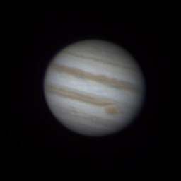
For example - this image was taken with 5" newtonian with spherical mirror (F/6.9):
That is remarkable level of detail for such scope and visual on such scope won't come anywhere near, but take any Jupiter image taken with any 5inch scope and you'll see about the same level of detail
-
6 minutes ago, Flame Nebula said:
Hi vlaiv,
Certainly a potent combo! I did see a used C11 for £1000 recently. Strangely, hardly ever see used C9.25 on astrobuysell though.
There could be a number of reasons for that, but the fact is - if both scopes are diffraction limited (and I'm guessing they should be in 95% of cases) - C11 is simply better imaging platform. You can't beat the laws of physics, larger aperture allows for sharper image.
-
1
-
-
C11, ED150 for photo and visual respectively
-
2
-
-
1 minute ago, Ags said:
I see it's possible to print in flexible plastics. I have some ideas for end-caps!
I've been both really positively surprised and somewhat disappointed in flexible plastics.
I think that TPU is great material given it's properties. It is very tough, very resistant, somewhat flexible (depending on type), but what I was disappointed about was that it does not have that rubbery feel to enhance grip. I considered it for ergonomic/grip surfaces of some parts.
Then I ran into this:
However, I haven't still had a chance to print with it. It looks like it has been specially designed for hta purpose.
-
1 hour ago, Ags said:
Only problem with online printing is the need to get the model right first time.
Or design in tolerances and features that makes use a bit flexible.
Here is aperture mask I designed for someone once:
It's a bit oversized - by 1 mm or so - just to make sure it will fit and I added 3 pockets for simple nuts so nylon tipped thumbscrews can be added to secure mask in place. They are also designed to be printed without supports with 45 degree overhang.
One could also design holder separately and have just few aperture mask inserts printed along it - no need for several masks. Saves on material use and shipping (I guess this last bit).
-
2
-
-
Here are some interesting points regarding exit pupil:
- telescope can't make extended objects brighter, only dimmer. The brightest view is with our naked eye. Exit pupil matched to our "entrance" pupil will give the same brightness of extended object as when viewed with naked eye. Smaller exit pupils will dim the object brightness for extended objects.
- Sky is also extended object. Contrast ratio, or ratio of target brightness to sky brightness can't be changed by a telescope. It is always the same. Only way to change this is by use of special filters (for example UHC filter if target is emission nebula).
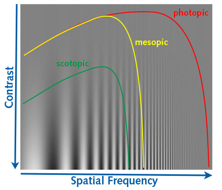
- Human vision is complex topic. Perceived contrast ratio depend on amount of light. It also depends on angular features of target - look at this image:
Frequency changes from left to right and contrast from on Y axis. It shows that not all frequency components are perceived the same although they have the same physical contrast (ratio of dark and light). This even changes with amount of light and our night vision adoption.
This is why we can "dial" in magnification for particular target and why larger scopes show faint fuzzies more easily - it is because of this combination of absolute levels of light + magnification. On physical level - small scope with exit pupil of 5mm delivers same amount of surface brightness as large scope with 5mm exit pupil.
-
3
-
-
5 at the moment.
8" F/6 Dob, 4" F/10 Achromatic refractor, 80mm F/6 APO triplet, 4" F/13 Maksutov, 8" F/8 RC
Well, 5 1/4
I have 80mm F/7.5 achromat being lens in a cell at the moment and trying to grow into full fledged OTA (waiting for me to get aluminum tubing and to 3d print a focuser for it).
-
9
-
-
1 hour ago, Neutrinosoup said:
and WO FLT98mm than I want to sell because I rarely use it.
Maybe you should try it first with ~40mm 2" eyepiece and a good 2" diagonal?
But you really want to wait for autumn for that target. It can be very high in the sky - near zenith (depending on your location).
For best results - wait for it to be near zenith and also check this website:
https://atmosphere.copernicus.eu/charts/packages/cams/products/aerosol-forecasts
This gives you forecast of transparency - you want "white" to be over your observing location for the evening you plan to observe. That is for best results of course.
Observing when dark gray is overhead is like observing with 8" telescope instead of 9" telescope - you loose one whole inch (going into yellow territory is even worse and can have effect of loosing 2" or more of aperture size!).
-
2
-
-
5 minutes ago, assouptro said:
would binning the stacked masters be as effective or do I need to start again at a base level for the best results?
I think that difference would be small if any, so you can simply bin the masters for simplicity.
-
 1
1
-
-
Very nice, but I think you have much more data in the image than it shows.
You could bin the data as it is over sampled to help with SNR, but that is a side note - look at this bit:
That is Holmberg IX - irregular dwarf galaxy that is satellite galaxy of M81 - it is there in the data but can't be readily noticed in the image the way it's been processed.
-
1
-


What's the grub screw for that's labelled 'do not touch' on the Redcat 51 v3 WIFD? Because it fell out on arrival!
in Discussions - Scopes / Whole setups
Posted
To me it looks like one of screws that holds focuser attached to the OTA, but I'm not sure (and that sort of seems logical as you need such screws but they are not listed on diagram).