


Jessun
-
Posts
2,132 -
Joined
-
Last visited
Content Type
Profiles
Forums
Gallery
Events
Blogs
Posts posted by Jessun
-
-
True. Legs are black on all versions. It's surprisingly solid btw!
-
-
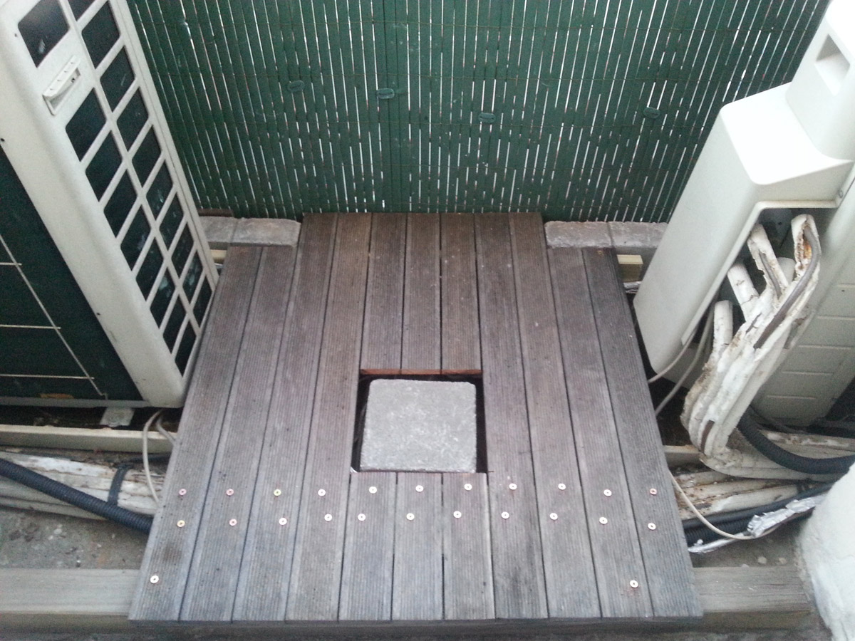
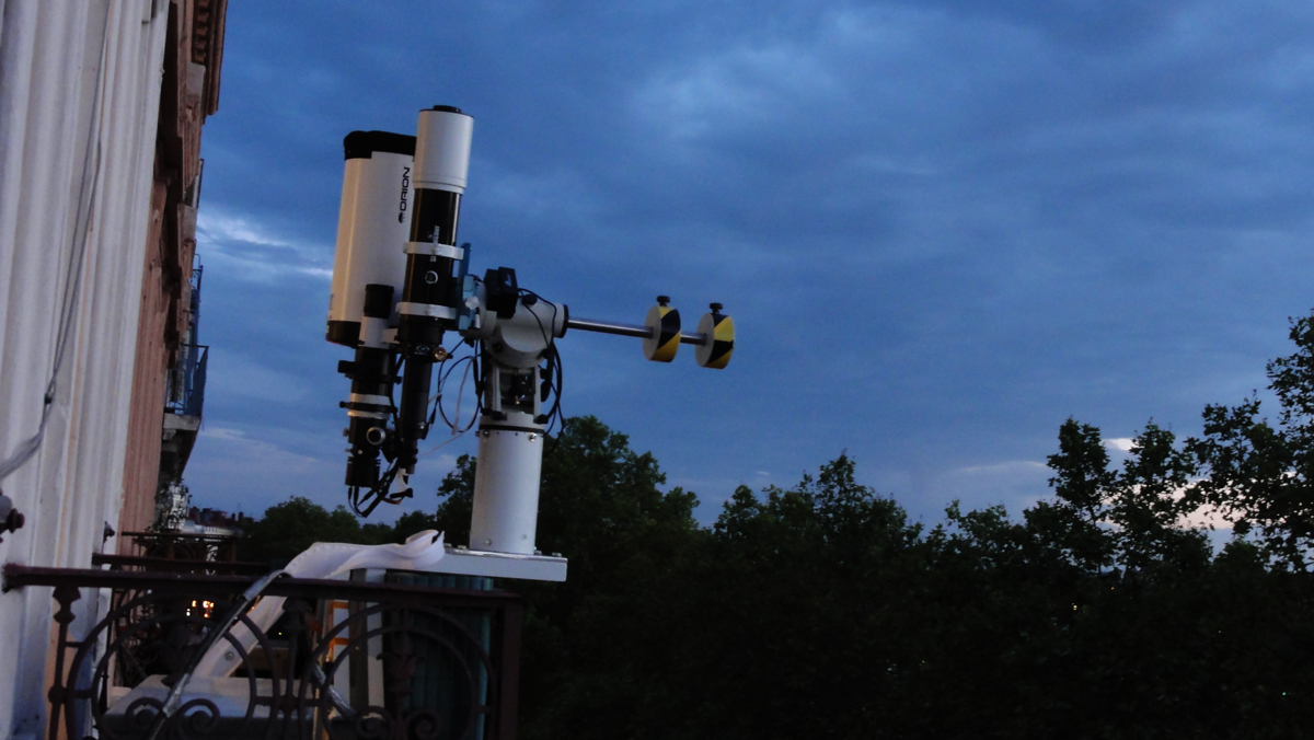
I put some slabs on the balcony, and made the wooden 'decking' floating. The wood had some sway to it so this made for a good improvement in how solid the thing sits out there.
It's going through a few alignment and guiding tests here as the sun sets. I'm racking up quite a few SW counter weights!!

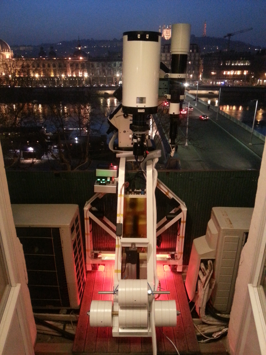
Looking forward to galaxy season!
/Jesper
-
 1
1
-
-
You could always go for a corrected Dall-Kirkham Sara, the secondary is spherical!
/Jesper
-
You sure have done the homework! Cheers for the links!
/Jesper
-
Fine review and excellent results John!
I think CF is just in fashion basically, it pops up everywhere these days. The Alu bars will do their thermal movements anyways. On the other hand the non CF versions have a steel tube - and Alu expands twice as much as steel, so no immediate gain there really. It comes down to that last pound of weight or so, and wether you like black CF or white paint...
A coupling between the bars and the tube that allowed differential expansion could be a money maker for the first company to sell them.
I have the 8" steel but am thinking of moving up to 10" in order to keep the same FL roughly - which I quite like - but at f5.4 instead of f8. Collimation is not second nature to me, but quite a few ouf you RC guys seem to have it nailed. May just ask one day how you did it...
/Jesper
-
The most you can reduce the 8"RC to as far as I know is about f5.4 using the AP CCDT67 reducer. This leaves you with a focal lenght of over one metre still, so on paper you're a lot closer to the 0.6m ED80, but problems grow quickly with added focal length.
Even reduced, the 8"RC can't really be regarded as a wide field scope. The Orion nebula for instance just about fits on a APS size CCD.
/Jesper
-
Haha, I know what you mean, but I've made sure to send 5 friends out there on a few occations
and they're still my friends! (They paid the price for being smokers...)They'd be about 400 kgs together. This is a mere 215 at the moment... And I can set it up with one hand!/Jesper
-
Yes Olly, this is a belt and braces approach to my rather rare problem. It's a solid piece of kit, and I've tried to cover any weaknesses. It's built with failure of any part in mind. Every single weld can be cut simultanously - gravity will hold it together. All wheels can snap - no problems. And now with steel reinforced flooring there will be no more colateral damage
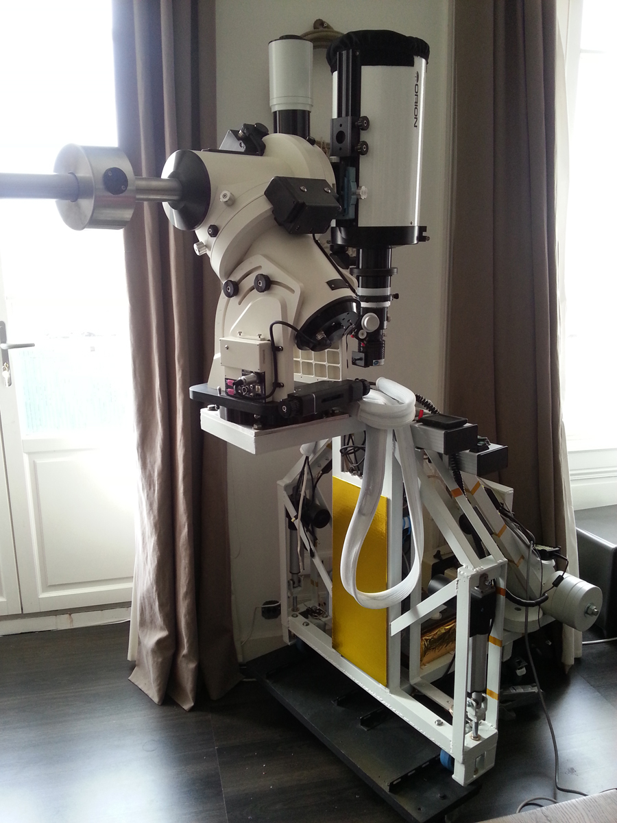
!Just to tie the thread up, here's the 'final' product, with the long awaited AP1600GTO sitting comfortably atop
 :
:
-
1
-
-
I've been working on the Crane to get it ready for the AP1600. It's not too much to do really, since I designed it with this mount in mind. It's just a matter of bolting on the flat surface adapter. The mount then slots straight in, and a few cables later I should be up and running. (I onle need the actual mount...)
On the photos above of the iOptron assembly you'll see the mount sat on a cut off pier section to reach the right height for the scope, allowing it to slew without catching. The AP1600 is so big that it will sit straight on the plate - no pier extender needed to reach the same height

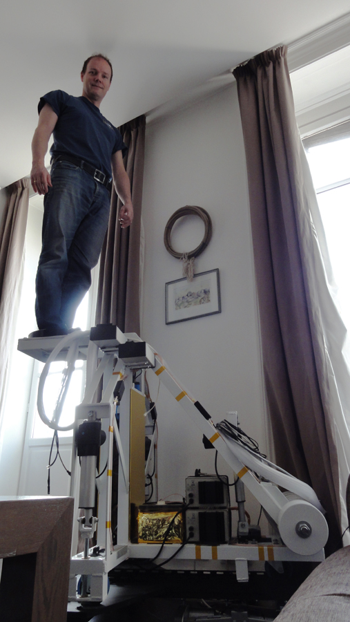
Will my construction hold the weight? I think so, but why not put it to the test!
-
It may well be worth trying to run the camera from a powered hub, just to make sure it get's the milliamps.
My Lodestar is extremely sensitive to this and a cable just a metre too long from the laptop will cause it to play up. In the case of the Lodestar it gets letterboxed. I solved it by using a shorter cable (i.e. the one actually supplied) but more recently by using an 'industrial' hub, that I power with 12V from one of the the inverters. Cables length and quality is no issue since.
/Jessun
-
This image was just a try out to see if it all worked OK etc
It works! Nice framing, and it's all there in great detail. I don't know about the banding but find that a healthy dither between the subs is always beneficial. Maybe with your camera too?
/Jesper
-
Yup! Very nice and clean!
Nothing like a DIY job finished

-
That has to be the coolest build I've seen on here
Kind comment, but this thing is born out of desperation of not having a better place to observe and image from. There are some really nice builds out there that I'd much rather have...
-
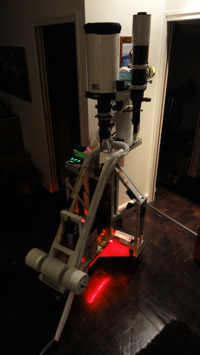
This was something I predicted, but it's still annoying. The Crane went through the floor. Luckily it was always designed to do just that, since I identified the floor as a potential hazard. So the Crane came to a rest on the support legs and could be jacked up by the actuators to salvage it.
I need to reinforce the floor now by some temporary means. A thin sheet of something, maybe even plywood oiled dark.
It is annoying, but it's still going strong all in all. The iOptron mount that sits on it for the time being plays up occationally in a random fashion, but the button PA works better than expected, and it is rock solid on the balcony. The iOptron is - apart from the floor giving in - by far the weakest link in my setup, also leaving the actual seeing and vis behind as a necessary evil.
The saying is Mount, Camera, Telescope, and I'm losing the plot on Mount... I may be asking too much from it, and will sell it soon, but it needs a v3 of some sort...
On that same night my AP photos hard drive died. Pretty much all work gone. I'm not crying tears over this as to be honest it was all rather mediocre but I had hopes to add data to some of the targets...
Ah, well! What can possibly go wrong now???

Here is the whole build:
-
1
-
-
Over the edge!
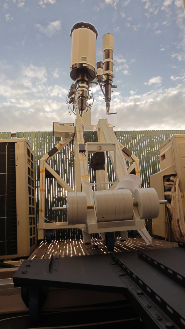
First test rollout!
It's been there before during the welding but not in one assembled piece and now the iOptron is in place. It sits on a cutoff verion of its original pier, but the little grub screws that used to hold it together have been replaced by 8 M10 bolts. Belts and braces!
I haven't jacked it up yet out there as the little piece of wooden decking - a whole 80*80cm - need some holes cut out and cement support blocks made to take the load of the three jack bolts.
The black thing down the bottom is the 'Crawler' that takes the Crane over the high threshold. Inside the flat the two become on unit that I can move about for parking it somewhere.
So far so good!
-
1
-
-
Hello elly12 and welcome to the forum!
The process of creation was one of improvisation. I have no scetches, just a paper with a few basic measurements. I started with the base. I made it T shaped so I could stand next to it on the limited space on the balcony. Then I put four bars to make the central 'pier'. It was made hollow for cable management. Next came the two main bent bars that extend over the edge. I made two rather than one beefy with the idea that the camera could go between the bars in a telescope park position - making a potentially large setup compact enough to clear the door frame.
At this stage the actuators were ordered, but I had no idea how to incorporate them. In the end I went for simplicity and I came up with a design that would be allowed to break without any major disasters - break due to dodgy craftmanship. The actuator frames on the sides also came to serve as stabilizers for the inner pier.
Improvisation then continued with the wiring and placement of control boxes.
So I wish there was a clever blueprint somewhere but I'm not good with that kind of stuff.
Thanks for looking and again welcome to SGL.
-
1
-
-
Cheers Dave!
Sounds like you need one of the same I have but the 300mm stroke lenght version (I use the 150mm ones). I belive the larger ones are 475 mm in the retracted position measured between the mounting holes.
http://www.gimsonrobotics.co.uk/GLA4000_12V-linear-actuator.html
They are not very fast so would take you 37 seconds to go end to end.
They work a charm, and are very quiet too.
Good luck with the build! Sounds interesting!
-
Yes. No. Prayers are for some other kind of forum
And the welds are redundant - just makes assembly easier. -
Here's an example of a common local design.... Not too heavy but from 10m up it would probably knock you to the ground should you have one land on your head

-
Thanks Steve! Looking at my maths a few posts up here, I think I need some luck too
... Let's just call it a typo.... -
My main focus is safety. I am not a welder so I had to work on the assumtion that any - or all - welded joints can break. As it is designed now gravity holds everytning in place apart from the top support for the jacks. If they fail catastrophically the rest of the structure will slide down the bolts - only half an inch - and land on rubber dampeners and the bottom support will lake the load - again held in place by gravity alone - the rubber is there to lessen the impact mainly with the mirrors in mind.
The two main top bars would still balance on the four middle legs even if all welds snapped - the scope and the ballast at the back will keep them from tipping anywhere. The ballast sits in place by gravity, but as a good measure an M20 rod holds them in place. (The 4 inner ones that is - the outer ones could in theory fall off if the M20 bolt snaps - but they are additional really and not needed to balance the thing.) These main bars consist of two full length angle profile that were heated and bent to form the knee. Again - no critical welds.
The OTA's have recessed safety stop bolts, plus an outer extra saddle that keeps it in place should it want to slip due temperature changes etc.
The CW's attach with an allen key, and the bar as a screw on safety stop. The Dyneema slings will be fitted in the event that the bar snaps or comes loose. I'm working under the assumption that if anything can happen in theory it will - so prevent it. Cameras and focusers will get the same safety sling.
All in all it's a design I worked on with one target only - nothing can ever be allowed to drop.
Looking up at what people stick out from their windows and balconies I can tell you that there are a lot of seriously heavy pottery looking far more dangerous to me...
-
At a maximum it will be Pier 130, Mount 50, Scope 50, CW and accessories 30 so about 280kgs. That really only equates to perhaps 4 quite slim people out there. I don't think it's at risk of collapsing even with 10 or 15 people on it - it would make everyone rather nervous about balconies if building regulations were that marginal... The balcony has a sturdy concrete filled metal frame.
I worry a bit more about the old wooden floor inside...
All will be secured with Dyneema slings, such as OTA, CW,s etc. Belt and braces all around!
-
looking forward to first light report!!
So do I! Sadly the iOptron threw all the toys out of the pram last time I used it so I need to make sure the mount actually works before putting any blame on the actual pier...
I know the pier fits on the balcony and clears the rail by a fraction of an inch - the rest is speculation so far... fingers crossed :-)


Skywatcher pillar for EQ6, why?
in Discussions - Mounts
Posted
Aha! Must be a rare collector's edition :-)
/Jesper