


strutsinaction
-
Posts
440 -
Joined
-
Last visited
Content Type
Profiles
Forums
Gallery
Events
Blogs
Posts posted by strutsinaction
-
-
When I had the same issue with my Tak 85, it was suggested to me that I should try offset focusing. Now, I was prepared to consider this on a camera lens or cheaper telescope but not on an instrument at this price point - that was not what I bought in to!
I expected a flat field on an 8300 sensor but that's not what I got so it went back. Perhaps my expectations were too high (?) but then, so too was the promise!
Offset focusing might be worth a try for you and if you are happy with the results - and many owners must be - then you have the solution. At least you can now rule out focus slop leaving you with CAA adjustment, sensor tilt or the plain fact that the field is not perfectly flat for your sensor size.
I hope this turns out to be an adjustment for you because the potential FOV of the Tak 85 makes it a very desirable instrument.
FSQ85 offset focussing mentioned here (courtesy of sharkmelley):
https://groups.yahoo.com/neo/groups/UncensoredTakGroup/conversations/topics/59070
I'm going to try this next time I'm out imaging.
Regards
John
-
If you decide to take your own issues further, then it would be interesting to hear what Mr King has to say. I use a different supplier.
If it's any consolation Steve I think my corner star elongation/distortion is worse than yours
 See my latest image here:
http://stargazerslounge.com/topic/256830-ngc281-pacman-hoo/
Jury still out on this for me (at least, nothing from Mr King or Takahashi yet), although I have my suspicions that in my case it could be due to poor focussing.
Regards
John
-
Hi John
If you decide to take your own issues further, then it would be interesting to hear what Mr King has to say. I use a different supplier.
Steve
I sent Ian King a few subs and he thinks this type of radial distortion at the corners is a collimation issue rather than mechanical tilt. He's sent my subs off to Takahashi Europe for further investigation. If they suspect a collimation issue then I'll have to return the scope to Ian for replacement or repair. In the meantime I still intend to do the zenith test when the skies clear.
Regards
John
-
I believe that that chip is physically smaller than the Kodak, correct? Whether or not you return your Tak is, of course, a matter for you. Are you happy with what it is doing in your corners? Have you tried the 5 second pointing at the zenith test?
Yes, smaller chip and, yes, I was happy until I started reading your thread and started pixel peeping
I will try the zenith test the next time it's clear.
Regards
John
-
... Are you using a KAF 8300 sensor?
No, I use a QSI690 (which was returned to QSI to get the Sony Glow fixed). Hoping I don't have to return my Tak!
Regards
John
-
...
The result is that I have ovoids present in at least 3 of the four corners of all images. To my mind the worst affected area in all images is the bottom right corner.
...
Just an idea. Maybe rotate your camera 90 degrees and repeat the test. If it's always the same bottom right hand corner that shows the most distortion then would that indicate sensor tilt?
I've been taking a closer look at some of my earlier images taken with the FSQ85. Coincidentally, I have elongated stars in the bottom right hand corner, more so that the other 3 corners. The other corners show some elongation but in different directions - radial I believe. This does not appear to be a PA issue. E-mail sent to Mr King for advice!
Regards
John
-
Hi SteveElongated stars in the corners may also be due to play in the CAA (camera angle adjuster). I assume you have the CAA in your optical train? See here for more info and a possible fix (if you are brave):The following may help too:I also have a Tak FSQ85 and have noticed elongated stars in one corner of my images and suspect the CAA, focuser slop or sensor tilt is the cause. It hasn't concerned me so far so haven't done anything about it but I may follow up with Ian King just in case this is a known issue.RegardsJohn
-
Congratulations, thoroughly deserved!
Regards
John
-
Almost?.....
Yes, almost, as in lacking the laptop and a cloudless, dark sky
-
Here's my Baby FSQ, almost ready for action.

-
 16
16
-
-
Fantastic achievement, well done and congratulations to you both. Looking forward to your next collaboration!
Regards
John
-
If you're interested, there's a similar thread on CN asking the same question:
http://www.cloudynights.com/topic/475406-considering-filter-thickness-when-calculating-backfocus/
Look for the post with the parts list where the supplier has quoted the backfocus contribution of the 3mm filter as -1.
Regards
John
-
Sadly, I don't have the final answer although my own current view flies against the advice from QSI - even though I use their camera - and that is simply because I believe that the critical distance requirement of correctors is based on an optical distance viewpoint (that assumes an air-filled void with a refractive index of 1 in the space between the corrector and the sensor) not a mechanical distance viewpoint and if we move the optical 'path' outwards then to me it follows that we need to move the optical 'distance' outwards to maintain the status quo!
Steve - isn't that what QSI are saying though? They state that the backfocus of the camera should be adjusted by -1mm if a 3mm filter is fitted. So, when you do the arithmetic to maintain the 72.2mm backfocus distance the contribution made by the camera is now reduced by 1mm to 49.2mm so you need to add a 1mm spacer to compensate, thereby moving the' optical distance outwards to maintain the status quo'.
Regards
John
-
Hi John,
I think you are right in that Astrodon and QSI are saying the same thing, just worded differently..... This means that behind the CA-35 Tak adaptor, it is expecting 55mm to CCD plane therefore the spacer needs to be 55-(50.2-1.0) = 5.8mm ? Do you concur?
Hi Nick
The optimum back focus for the Tak x0.73 reducer is quoted as 72.2mm. The CA-35 (SKY90) adapter is 16mm and the back focus of the QSI690 is 50.2mm. So, without adding a filter into the mix the custom T-mount adapter needs to contribute 72.2-16-50.2=6mm. I purchased this customer T-mount adapter from Ian King specifically for this case.
If I'm using a 3mm then I have 2 options:
- If I want to maintain the geometric back focus distance I'd need to add a 1mm spacer. This I can do. I also think I wouldn't need to refocus.
- If I want to maintain the optical back focus distance then I think I'm stuck because I can't remove 1mm from the custom T-mount adapter (unless I buy a lathe
). I guess the T-mount should have been manufactured 1mm shorter so it could be used with and without 3mm filter (for the latter I would simply need to adda a 1mm spacer). With this option I'd also have to refocus.For me, this is all hypothetical anyway, and don't think the 1mm would make much difference. Who knows. As Andrew correctly points out, there are other optical elements that would also need to be accounted for too, like the CCD window and coverplate, which Astrodon also mentions on his website.
I would also like to thank Andrew for his valuable insight. I'm not sure what his background is, but it sounds like he knows what he's talking about. I'm still learning
Regards
John
-
It's all gone quiet on this thread, so let me open it up again having done some more research
The following is taken from Astrodon's website where Don refers to backfocus and the use of a 3mm Astrodon filter:
"There may be some confusion as camera manufacturers measure backfocus from the focal plane of the CCD to the outer surface of the camera. When they account for the thickness of the filters, they SUBTRACT 1mm, which is correct as measured from the CCD. However, most people measure backfocus from the back of their scope or from a corrector, and then add/subtract spacers to arrive at the correct backfocus. In this case, as measured from the scope, the 1mm must be ADDED. A subtle point, but does get people in trouble from time to time."
Now on the QSI website they state that the backfocus of the QSI690 is 50.2mm as measured from the focal plane of the CCD to the outer surface of the camera. They then go on to say that when used with a 3mm filter you subtract 1mm from this backfocus distance i.e. 49.2mm.
So, this indicates that Astrodon and QSI agree, does it not?
In my case, to maintain the 72.2mm optical backfocus when using the x0.73 reducer with a 3mm Astrodon filter, I'd have to add a 1mm spacer to my custom T-Mount.
Regards
John
-
I'm with Ollie on this.
I can understand that there's an optimum design spacing between the reducer and CCD chip. I would have thought that this was simply the optical distance to the new focal plane and assumes that the optical train is in air with a refractive index of 1 and no filters.
If you then add a filter between the reducer and CCD then the optical path increases so that the new focal plane is further away than the original focal plane and so the optimum design spacing is now increased. If you keep the optical path the same then surely the light rays from the filter will no longer converge at the CCD?
I'm sure a light ray diagram would clear this up!
Regards
John
-
I've changed my mind again and am now in the 'add' rather than 'subtract' camp
Andrew's ray diagram is too compelling, So, my Tak x0.73 reducer + QSI690 calculation is a follows:When using the reducer, the back focus distance from the reducer to the CCD imaging plane should be 72.2mm. The CA-35 (SKY90) is 16.0mm and the QSI-690 back focus distance is 50.2mm when fitted with the standard T mount adapter plate. Therefore, a custom Wide T Mount needs to add 6mm to the back focus. When fitted with filters, the back focus distance increases by a third of the thickness of the filter. The Baader LRGB 1.25" filters have a width of 2.1mm which adds 0.7mm to the back focus i.e. 72.9mm. The Astrodon NB 1.25" filters have a width of 3.0mm which adds 1mm to the back focus i.e. 73.2mm. Therefore, assuming the custom Wide T Mount adapter contributes 6mm to the back focus an additional 0.7mm needs to be added using a spacer when using a Badder filter and 1.0mm when using an Astrodon filter.I'm not sure the 0.7mm or 1mm would make any difference anyway but I'd still like to know if my calculation is correct nonetheless!RegardsJohn -
Agreed, Andrew. You subtract only when you need to maintain a fixed distance between a reducer/corrector and CCD.
For example, consider my case - Tak x0.73 + QSI690.
When using this reducer, the back focus distance from the reducer to the CCD imaging plane should be 72.2mm. The CA-35 (SKY90) adapter is 16.0mm and the QSI-690 back focus distance is 50.2mm when fitted with the standard T mount adapter plate. Therefore, the customer Wide T Mount (supplied by IKI) needs to add 6mm to the back focus.However, when fitted with filters, you need to subtract a third of the thickness of the filter from the backfocus distance of the QSI-690. The Baader LRGB 1.25" filters have a width of 2.1mm which removes 0.7mm from the backfocus of the QSI-690 i.e. 71.5mm. The Astrodon NB 1.25" filters have a width of 3.0mm which removes 1mm from the backfocus of the QSI-690 i.e. 71.2mm. Therefore, the Wide T Mount adapter needs to add 5.3mm (72.2-16.0-50.2-0.7) when using a Badder filter and 5.0mm (72.2-16.0-50.2-1.0) when using an Astrodon filter.I thinkRegardsJohn -
Thanks, Merlin66. The QSI document now makes sense to me. So, in the case of a 3mm Astrodon, the filter adds 1mm to the light path so you have to subtract this 1mm from the physical backfocus measurement to maintain the fixed backfocus distance (in my case a x0.7 reducer).
Regards
John
-
I would also tend to agree with Andrew and his ray diagram. This is GCSE physics, isn't it? Light rays entering the filter are bent towards the normal, then away from the normal on exiting the filter, so that both the incident light and emergent rays are parallel and the focus point is further away.
I read the QSI back focus document a while ago and didn't think too much about it but surely it's wrong to subtract. Interesting stuff!
Regards
John
-
Hi
It does actually say that. You can download the smaller indexes if you like and see which ones AT actually use to solve

You can download them all if you really want!
Louise
Just for the fun of it, I downloaded them all for my local Astrometry.net install for SGPro. 32GB I think! Most of them are redundant. To speed up platesolving I only use a small subset (as reported by the ANSVR log file).
Regards
John
-
Cheers for that Louise
Looks like is misread the tutorial...I thought you put in 20% of your minimum FOV, not take 20% off and use 80%.
Will adjust my setup accordingly and see what difference that makes to it
Hmm. I thought the Light Vortex tutorial states that you should take 20% of the smallest FOV. I quote:
For example, let us say that I only have the Borg 77EDII telescope and QSI 660i CCD camera. We calculated the field of view to be 1.95 degrees x 1.56 degrees for this setup. We therefore take our widest field of view here to be 1.95 degrees and the narrowest to be 1.56 degrees. 20% of the narrowest is then 0.312 degrees (or 18.72 arcminutes, multiplying by 60) and we have our numbers for selecting appropriate astrometric index files.
So, shelster1973, I think your original calculate is correct.
Regards
John
-
Not sure how missed this thread. Stunning work. Looking forward to your next contribution!
Regards
John
-
Hi
Already posted in this section but this is my first ever DSO so no harm in adding an entry to this thread too!
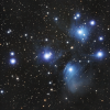 Lum 20x60s 1x1, RGB 20x60s 2x2, sequenced and captured with SGPro and processed with PixInsight and Photoshop Elements.RegardsJohn
-
2
-


Ovoids with Mesu and Tak FSQ 85
in Imaging - Image Processing, Help and Techniques
Posted
That's what I was thinking and something I will try. It just seems odd though.
Regards
John