


Gina
-
Posts
45,326 -
Joined
-
Last visited
-
Days Won
120
Content Type
Profiles
Forums
Gallery
Events
Blogs
Posts posted by Gina
-
-
For the remote control I plan to use similar code to the Astroberry Focuser INDI Driver code but applied to a separate INDI driver as the Astroberry Focuser is already in use for focussing the lens. Like the Focuser Driver, the new driver can have preset values as well as general control. These saved presets can hold the angles for a series of panels for a mosaic. Once set up the driver code in Ekos will retain the camera rotation position just as the focuser retains the focus position. This should mean that I won't need to provide endstop switches.
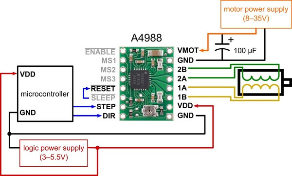
GPIO 25 has a pull-down so suitable for the STEP line. SLEEP could also do with pull-down. DIR doesn't matter. These could go on GPIO 20 and 21.
-
 1
1
-
-

Minimal wiring diagram for connecting a microcontroller to an A4988 stepper motor driver carrier (full-step mode).
This shows that only two data lines need connecting to the RPi GPIO. It does also need Vdd (3.3v) and Data Gnd connections to the HAT plus the 12v and power Gnd for the motor. However, I suspect that the driver may supply a "holding current" to the motor which isn't required in this case so the SLEEP line can be used to turn the current off.
-
1
-
-
There's just about room to get the A4988 driver etc. in the electronics box. The RPi+HAT comes out easily enough so I shall be able to add connections to the GPIO pads on the HAT. Strip board with A4988 can be attached to the side of the box with hot melt glue. Photo shows A4988 stepper driver module and board placed where there's space.
-
1
-
-
This photo shows the assembled imaging rig. There wasn't enough room to get a shaft coupler between motor and first worm so I decided to combine worm and coupler by designing and printing a new worm as shown in the CAD screenshot below. The worms were made to be a tight fit on the shaft and the first worm was fixed to the motor shaft with a grubscrew.
With the right stepper motor. The lens etc. for the second camera is yet to be added.
-
1
-
-
Changed nozzle to 0.4mm (from 0.6mm) and printed the worms and worm gears. Went well. The black thing is nothing to do with the rig - just about the right height to hold the gear in correct mesh with the worm.
Now printing a slightly modified base part :-
-
1
-
-
This shows the rig moved to the right, with the stepper motor moved to the end of the dovetail, to make room for the guider to be attached to the dovetail on the left.
-
1
-
-
Now to the worm axle, stepper motor and back end bearing.
-
1
-
-
A couple of design improvements and changes to make construction easier. The camera supports have a "rim" added to extend the bearing surfaces and for the gears to rest against to stop the cameras moving axially. The base back has been lowered to give access to screws to attach the front camera brackets and camera bracket extended to match.
-
1
-
-
Here are some CAD screenshots of the worm drive system from various angles and some with hidden parts to show the details of the drive system.
-
1
-
-
To make the CAD model easier to understand, I have coloured the parts. As with the other thread I have shown the cooling vents on the cameras as a hole through it. The idea was to make sure there was plenty of space for the cooling airflow to escape.
Having thought about the construction I came to the conclusion that the worms would be better between the cameras and the dovetail bar so looked into doing this. Next CAD screenshots of the assembly show what needed to be done. Raising the cameras away from the dovetail bar around 16mm provided room for the worms. The advantage is that the stepper motor could be mounted directly on the dovetail bar and the back end bearing with a bracket on the base part. Moving the cameras by 16mm didn't seem too big a "price to pay" for the advantage of having the worms easier to mount.
-
1
-
-
The first thought was to arrange the worm drive above the cameras where there is plenty of room, with the drive motor and back end bearing on separate pillars attached to the dovetail bar.
This CAD model shows the worm drive system. The worm has been extended a bit and and extra conical and cylindrical part added to take a grub screw and the worm gear edited to clamp round the body of each camera.
-
2
-
-
Following 3D printing problems with the triple imaging rig, I've decided to design a totally different dual NB widefield imaging rig. Well, not totally different I guess, it still uses ASI1600MM-Cool cameras, Astrodon 3nm NB filters and vintage film SLR lenses with remote focussing. The difference is that there will only be two cameras etc. and the rotation system will use worm gear drive rather than spur gears. This is a method I've been wanting to try, giving easier to calculate motor steps for each angle. It also allows me to try out worm drive which I've never 3D printed before.
Instead of using a single printed camera support panel front and back which failed to print properly, this design uses individual camera brackets attached to a U shaped base part.
-
1
-
-
Getting severe warping even with PLA so until I solve this problem I am abandoning the triple imaging rig design and going for a different design of dual imaging rig. With so much difference I think I'll start a new thread.
-
 1
1
-
-
I use white PLA for my astro imaging rigs, including All Sky Camera which stays out in the elements all year round. No problems with degrading as yet. It seems to last better in sunlight than commercial ABS or PET items which seem to disintegrate very quickly. Even in the UK!!!
-
1
-
-
This shows the size of the camera mounting plates compared with the bed size of my 3D printer. This is the front plate which takes the camera rotation stepper motor.
This is one of the camera rotation gears on a camera.
More parts added to the assembly model. The focus systems are missing the little stepper motors with pinions as can be seen in the photo.
-
5
-
-
Made a mistake - should have said Mesh Grid Compensation and "Show Mesh Grid Heightmap". Is that makes any difference.
-
I know there are others here using the excellent Duet WiFi control board and probably Firefox to control it. Since a recent upgrade of Firefox I am getting a JavaScript error when trying to show the "Auto Bed Compensation" results. Screenshot below. Anyone know what I can do to stop this error and show the bed levelling results, please?
-
No warping and has printed well. I shall be bringing my imaging rig indoors a bit later to see how things fit. I have also printed one of the camera gears.
-
1
-
-
Printing the front plate. ).8mm nozzle and 0.5mm layer height.
-
1
-
-
22 hours ago, teoria_del_big_bang said:
Do you intend the final rig to be 3D printed in plastic or do you think it will need to be machined ?
Can't wait to see your progress with this it really does interest me.
Steve
Thanks Steve. I intend this to be 3D printed.
-
1
-
-
I wondered about temperature changes myself. All I can do is "suck it and see" I think
-
1
-
-
I have had various thoughts but the camera bodies seem to turn quite smoothly on 3D printed PLA so I'm trying that initially. This is definitely an experimental project so u8pgrades may be required.
-
2
-
-
You are right - forgot to mention that. The gears stop cameras sliding forward and I shall be adding detachable plates to stop sliding backwards.
-
 1
1
-
-
Here are a couple more screenshots showing the complete assembly with both camera mounting plates, dovetail and most of the parts. Cables and connectors left out for clarity (well that's what I'm saying 🤣) Same with the remote focussing which clamps round the lenses. May add that later as it is relevant.
-
2
-


Dual Widefield NB Imaging Rigs with Remote Rotatable Cameras - Worm Drive.
in DIY Astronomer
Posted
Wiring for the camera rotation A4988 finished.